Download
1 / 47
470 likes | 572 Views
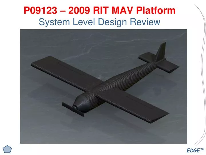
P09123 – 2009 RIT MAV Platform System Level Design Review. 2009 MAV Team Members. Basic Project Information. Project Number and Name P09123 Micro Aerial Vehicle (MAV) Platform Project Family Micro Aerial Vehicle Track Aerospace Systems and Technology Start Term 2009-1 End Term

E N D
Basic Project Information Project Number and Name P09123 Micro Aerial Vehicle (MAV) Platform Project Family Micro Aerial Vehicle Track Aerospace Systems and Technology Start Term 2009-1 End Term 2009-3 Faculty Guide Dr. Jeffery Kozak (Mechanical Engineering) Faculty Consultants Dr. Agamemnon Crassidis (Mechanical Engineering) Dr. Hany Ghoneim (Mechanical Engineering) Primary Customer Dr. Jeffery Kozak, RIT MAV Team Secondary Customer Impact Technologies
Product Description /Project Overview Mission Statement: The MAV Family of Projects: To build a semi-autonomous, tending towards full autonomy, air vehicle that will be used in the future for Multidisciplinary Senior Design and for graduate studies in the college of engineering and the college of imaging science. To have a hands on aeronautical project for undergraduate students that is of low cost and simplicity as to be able to be made by hand. To provide an incentive for students as well as exposure of engineering at RIT by competing in the more aggressive United States/Europe MAV competition The P09123 Project will: Develop the Platform for an expandable and re-useable Micro Aerial Vehicle (MAV) that is intended to be used as a basis for current and future MAV design.
Concept Generation - Propulsion Excellent Good Satisfactory Poor Gas Batteries Solar Cells Super Capacitor Jet Turbine Rocket
Basic Subsystem Layout – “The Diagram” Tail Assembly: -Vertical Stabilizer -Horizontal Stabilizers -Control Servos Equipment Cage: -R/F Electronics -GPS -Microcontroller -Batteries Fuselage Nose Cone Assembly: -Propulsion -Motor/Controller -Propeller Wing Assembly (2): -Airfoil -Control Surfaces -Control Servos
MAV Subsystem Breakdown • Propulsion • Thrust Requirements • Propeller • Motor and Controller • Nose Cone Design • Control Surfaces • Servo Actuation • Size, Shape, Function • Material • Location • Fuselage • Material/Construction • Structure • Integration • Wings/Airfoil • Airfoil Shape • Tail Design • Flight Dynamics • Aerodynamics • Material/Construction
MAV Subsystem Breakdown • Process Development • Manufacturing Process • Final Assembly • Documentation • Procurement • Bill of Materials/Cost Analysis • Analysis/Testing • Flight Testing • Wind Tunnel Testing • CFD/FEA • Material Testing • Simulation • Equipment Cage • Structural Integrity • Hardware Mounting • Protection • Vibration Damping • Electronics • Batteries • R/C Elements • Motor Controller • Power Requirements • Servo Control
Aaron Nash AIRFOIL ANALYSIS
2009 MAV Airfoil & Wing Design Assumptions • Velocities • VCruise = 20 mi/hr, Ma = 0.026 • VMax = 35 mi/hr, Ma = 0.046 • VMin = 10 mi/hr, Ma = 0.013 • Chord = 6 inches Reynolds Number Calculations • ReCruise = 10312 • ReMax = 180482 • ReMin = 51581.55 Look for Low Reynolds Number Airfoils!
Coefficient Calculations • Minimum Coefficient of Lift Calculation • Assuming a span of three feet and a weight of 3.31 lbs (1.5 kg) • Clmin = 2.1564 (v = 25 mph) • Clmin = 0.7041 (v = 35 mph) • Clmin = 8.62 (v = 10 mph)
UIUC Database Selected a number of low Reynolds Number Data Airfoils Benchmarked from P08121 Results can be seen in handout Airfoils
Selig s1210 2nd highest Lift Coeff Highest operating envalope Between 2 and 9 degrees AoA Selig s1223 Highest Lift Coeff Operating Point at 2 degrees AoA Airfoil Selection
Wing will be positioned on the top of the fuselage Creates a pendulum effect Uses the weight of the fuselage to provide natural lateral stability Keel Effect Tapered wing tips to add “virtual span” Wing position
FUSELAGE Joe Hozdic
2009 MAV Fuselage • Material: Carbon/Kevlar Biaxial Sleeve Woven Carbon Cloth Wings Attach To Protrusion Cage Structure Contained in Body
Wing Attachment Concepts Thru Pin Adhesive • Adhesive • Strong Connection • Permanent • No Affect on Aerodynamics • Pinned Joint • Relatively Weaker • Removable • May Affect Aerodynamics
Cage Location • Cage may be adjusted front to back: • Shifts center of gravity • Compensates for various configurations
Equipment Cage Assembly Foam Isolators: Secure Cage Inside Fuselage Protective Cage: Carbon or Aluminum Rods Components will attach either directly to cage or the voids may be filled with a thin sheet of plastic/composite to mount equipment on
WING STRUCTURE Corey Kulcu-Roca
Skin Materials • Monokote • Carbon /Kevlar • Fiberglass • Carbon fine weave
Wing Core Materials • Foam • Carbon Ribs • Balsa Wood • Honeycomb • Carbon Rod
PROPULSION Brian David
Propulsion Components Motor 7.8 V 32000 RPM 5.7 W .8 oz Battery 7.4 V 600 mAh 1.3 oz Propeller 5.1x4.5 APC E Hub ID = .25” .00125 oz
Propulsion Calculations Thrust 7.40*.60=4.44 W 4.44/4.70=.947 .947*32000=30230 RPM Max RPM = 190000/D = 37255 RPM 30230 < 37255 OK From thrust calc: Thrust at 30230 RPM = 1.66 Kg Power to weight ratio Max Thrust / Max Weight 1.66 / 1.5 = 1.1
Flight Time Full Throttle P / V = current draw 4.7 W / 7.8 V = .603 A 600 mAh / .603 A = 59.7 min 4.8 V cutoff voltage 7.4 / 4.8 = 1.54 59.7 min / 1.54 = 38.8 min
Joe Chow MANUFACTURABILITY
Concept Development- Structure Diagram SA-1 Propeller SA-2 Motor Nose Cone SA-2-1 Electronics Cage L. Horizontal Stabilizers SA-2-2 Elevator MAV Fuselage + Tail Stock R. Horizontal Stabilizers Elevator SA-2-3 Vertical Stabilizers SA-2-4 Rudder Servos SA-3 Aileron Wings (2)
Concept Development RISK ASSESSMENT
Concept Development SCHEDULE