Download
1 / 52
520 likes | 620 Views
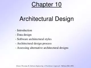
Chapter 10 Architectural Design. Software Engineering: A Practitioner’s Approach, 6th edition by Roger S. Pressman. Software Architecture.

E N D
Chapter 10Architectural Design Software Engineering: A Practitioner’s Approach, 6th edition by Roger S. Pressman
Software Architecture • The software architecture of a program or computing system is the structure or structures of the system, which comprise the software components, the externally visible properties of those components, and the relationships among them. — Bass. et al.
Why Architecture? • Architecture is a representation of a system that enables the software engineerto: • analyze the effectiveness of the design in meeting its stated requirements, • consider architectural alternatives at a stage when making design changes is still relatively easy, and • reduce the risks associated with the construction of the software.
Data Design • Architectural level Database design • data mining • data warehousing • Component level Data structure design
Architectural Styles • Each style describes a system category that encompasses: • a set of components (e.g., a database, computational modules) that perform a function required by a system, • a set of connectors that enable “communication, coordination, and cooperation” among components, • constraints that define how components can be integrated to form the system, and • semantic models that enable a designer to understand the overall properties of a system.
Specific Styles • Data-centered architecture • Data flow architecture • Call and return architecture • Object-oriented architecture • Layered architecture
Independent Component Style Client A Client B Server Client C Client D Peer W Peer X Peer Y Peer Z
Architectural Patterns • Concurrency • operating system process management • task scheduler • Persistence • database management system • application level persistence • Distribution • broker
Architectural Design • Architectural context diagrams model how software interacts with external entities • Archetypes are classes or patterns that represent an abstraction critical to the system • Architectural components are derived from the application domain, the infrastructure, and the interface.
Example Archetypes in Humanity Addict/Gambler Amateur Beggar Clown Companion Damsel in distress Destroyer Detective Don Juan Drunk Engineer Father Gossip Guide Healer Hero Judge King Knight Liberator/Rescuer Lover/Devotee Martyr Mediator Mentor/Teacher Messiah/Savior Monk/Nun Mother Mystic/Hermit Networker Pioneer Poet Priest/Minister Prince Prostitute Queen Rebel/Pirate Saboteur Samaritan Scribe/Journalist • Seeker/Wanderer • Servant/Slave • Storyteller • Student • Trickster/Thief • Vampire • Victim • Virgin • Visionary/Prophet • Warrior/Soldier (Source: http://www.myss.com/)
Example Archetypes in Software Architecture Node Detector/Sensor Indicator Controller Manager Moment-Interval Role Description Party, Place, or Thing (Source: Pressman) (Source: Archetypes, Color, and the Domain Neutral Component)
Analyzing Architectural Design 1. Collect scenarios. 2. Elicit requirements, constraints, and environment description. 3. Describe the architectural styles/patterns that have been chosen to address the scenarios and requirements: • module view • process view • data flow view 4. Evaluate quality attributes by considered each attribute in isolation. 5. Identify the sensitivity of quality attributes to various architectural attributes for a specific architectural style. 6. Critique candidate architectures (developed in step 3) using the sensitivity analysis conducted in step 5.
An Architectural Design Method customer requirements "four bedrooms, three baths, lots of glass ..." architectural design
Deriving Program Architecture Program Architecture
Partitioning the Architecture • “horizontal” and “vertical” partitioning are required
Horizontal Partitioning • define separate branches of the module hierarchy for each major function • use control modules to coordinate communication between functions function 3 function 1 function 2
Vertical Partitioning:Factoring • design so that decision making and work are stratified • decision making modules should reside at the top of the architecture decision-makers workers
Why Partitioned Architecture? • results in software that is easier to test • leads to software that is easier to maintain • results in propagation of fewer side effects • results in software that is easier to extend
Structured Design • objective: to derive a program architecture that is partitioned • approach: • the DFD is mapped into a program architecture • the PSPEC and STD are used to indicate the content of each module • notation: structure chart
Flow Characteristics Transform flow Transaction flow
General Mapping Approach isolate incoming and outgoing flow boundaries; for transaction flows, isolate the transaction center working from the boundary outward, map DFD transforms into corresponding modules add control modules as required refine the resultant program structure using effective modularity concepts
First Level Factoring main program controller output input processing controller controller controller
Transaction Flow incoming flow action path T
Transaction Example fixture fixture setting servos commands operator process report display operator screen commands robot control robot control software assembly record in reality, other commands would also be shown
Refining the Analysis Model write an English language processing narrative 1. for the level 01 flow model apply noun/verb parse to isolate processes, data 2. items, store and entities develop level 02 and 03 flow models 3. create corresponding data dictionary entries 4. refine flow models as appropriate 5. ... now, we're ready to begin design!
Deriving Level 1 Processing narrative for " process operator commands" Processing narrative for " process operator commands" Process operator command software reads operator commands from the cell operator. An error message is displayed for invalid commands. The command type is determined for valid commands and appropriate action is taken. When fixture commands are encountered, fixture status is analyzed and a fixture setting is output to the fixture servos. When a report is selected, the assembly record file is read and a report is generated and displayed on the operator display screen. noun-verb When robot control switches are selected, control values are sent to parse the robot control system. Process operator command software reads operator commands from the cell operator . An error message is displayed for invalid commands . The command type is determined for valid commands and appropriate action is taken . When fixture commands are encountered , fixture status is analyzed and a fixture setting is output to the fixture servos . When a report is selected, the assembly record file is read and a report is generated and displayed on the operator display screen . When robot control switches are selected , control value sent to s are the robot control system.
Transaction Mapping Principles isolate the incoming flow path define each of the action paths by looking for the "spokes of the wheel" assess the flow on each action path define the dispatch and control structure map each action path flow individually