Download
1 / 1
10 likes | 136 Views
10 in. 10 in. 1. 2. .375 in. .5 in. .5 in. 0.25 in. Rules of Thumb in Assembly:. 0.5 in. 0.5 in. 3b. 3b. 3b. 0.75 in. 0.75 in. Assemble with 8 aluminum pop rivets as shown. Part 2 should fit inside Part 1, lined up with rivets holes

E N D
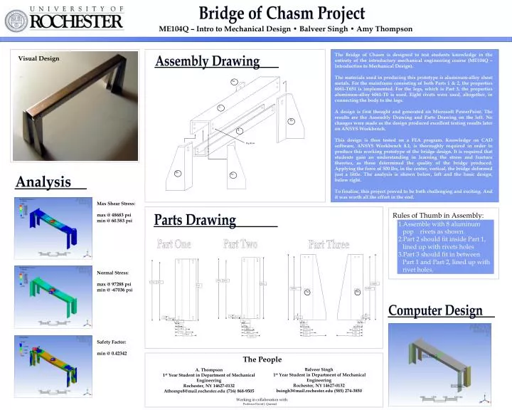
10 in. 10 in. 1 2 .375 in. .5 in. .5 in. 0.25 in. Rules of Thumb in Assembly: 0.5 in. 0.5 in. 3b 3b 3b 0.75 in. 0.75 in. • Assemble with 8 aluminum pop rivets as shown. • Part 2 should fit inside Part 1, lined up with rivets holes • Part 3 should fit in between Part 1 and Part 2, lined up with rivet holes. 1.0 in. 1.0 in. 1.5 in. 1.5 in. 3a 1.75 in. Pop Rivet 3a 9.75 in. 9.5 in. 9.75 in. 9.5 in. 3.625 in. 3.375 in. 3.375 in. Part One Part Two Part Three .25 in. .25 in. .25 in. .125 in. .5 in. 1.25 in. .5625 in. 1.5 in. 1.0625 in. 1.3125 in. .25 in. 0.25 in. 0.5 in. 0.5 in. Bridge of Chasm Project ME104Q – Intro to Mechanical Design • Balveer Singh • Amy Thompson The Bridge of Chasm is designed to test students knowledge in the entirety of the introductory mechanical engineering course (ME104Q – Introduction to Mechanical Design). The materials used in producing this prototype is aluminum-alloy sheet metals. For the mainframe consisting of both Parts 1 & 2, the properties 6061-T651 is implemented. For the legs, which is Part 3, the properties aluminum-alloy 6061-T0 is used. Eight rivets were used, altogether, in connecting the body to the legs. A design is first thought and generated on Microsoft PowerPoint. The results are the Assembly Drawing and Parts Drawing on the left. No changes were made as the design produced excellent testing results later on ANSYS Workbench. This design is then tested on a FEA program. Knowledge on CAD software, ANSYS Workbench 8.1, is thoroughly required in order to produce this working prototype of the bridge design. It is required that students gain an understanding in learning the stress and fracture theories, as these determined the quality of the bridge produced. Applying the force of 500 lbs, in the center, vertical, the bridge deformed just a little. The analysis is shown below, left and the basic design, below right. To finalize, this project proved to be both challenging and exciting. And it was worth all the effort in the end. Visual Design Assembly Drawing Analysis Max Shear Stress: max @ 48683 psi min @ 60.583 psi Parts Drawing Normal Stress: max @ 97288 psi min @ -67036 psi 3a Computer Design Safety Factor: min @ 0.42342 The People Balveer Singh 1st Year Student in Department of Mechanical Engineering Rochester, NY 14627-0132 bsingh3@mail.rochester.edu (585) 274-3850 A. Thompson 1st Year Student in Department of Mechanical Engineering Rochester, NY 14627-0132 Athomps8@mail.rochester.edu (716) 868-9505 Working in collaboration with: Professor David J. Quesnel