Download
1 / 54
540 likes | 546 Views
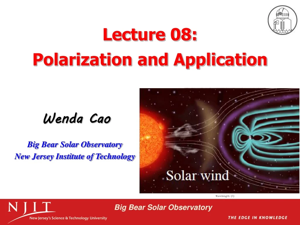
Lecture 08: Polarization and Application. Wenda Cao. Big Bear Solar Observatory New Jersey Institute of Technology. Outline. Nature of Polarized Light Polarizers Retarders Mathematical Description of Polarization Solar Magnetic Field Measurement Techniques Example 1 - DVMG

E N D
Lecture 08: Polarization and Application Wenda Cao Big Bear Solar Observatory New Jersey Institute of Technology
Outline • Nature of Polarized Light • Polarizers • Retarders • Mathematical Description of Polarization • Solar Magnetic Field Measurement Techniques • Example 1 - DVMG • Example 2 - IRIM Textbook: Optics, Eugene Hecht Solar Magnetic Fields, Jan Stenflo
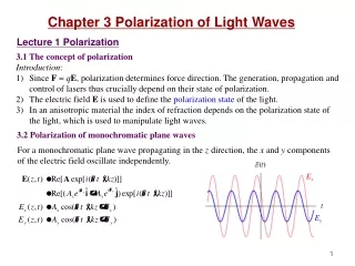
1. Nature of Polarized Light • Light may be treated as a transverse electromagnetic wave • Imagine two harmonic, linearly polarized lightwaves of the same frequency, moving through the same region of space, in the same direction • is the relative phase difference between the waves. Ey lags Ex when > 0; Ey leads Ex when < 0 • Linear Polarization • Circular Polarization • Elliptical Polarization • Natural Light
Linear Polarization • If = 2m, and m = 0, 1, 2, …, the waves are in-phase, • If = m, and m = 1, 3, 5, … an odd integer, the two waves are 180 out-of-phase, • Any plane-polarized wave can be resolved into two orthogonal components.
Circular Polarization • If E0x = E0y = E0 and = -/2 +2m, m = 0, 1, 2, …, the consequent wave is • Scalar amplitude of E is a constant, but the direction of E is time-varying. • The resultant electric-field vector E is rotating clockwise at an angular frequency of , as seen by an observer toward whom the wave is moving. Such a wave is right-circularly polarized • If E0x = E0y = E0 and = /2 +2m, m = 0, 1, 2, …, the consequent wave is • A linearly polarized wave can be synthesized from two oppositely polarized circular waves of equal amplitude,
Elliptical Polarization • Both linear and circular light may be considered as special cases of elliptically polarized light, • After expanding and rearranging terms, we have • This is the equation of an ellipse making an angle with (Ex, Ey)-coordinate system • When = /2, 3/2, 5/2… • When = 2, 4, 6…
State of Polarization • Linearly polarized or plane-polarized light can be represented as a superposition of right- and left-circular states • Elliptical light can also be represented as a superposition of right- and left-circular lights.
Natural Light • An ordinary light source consists of a very large number of randomly oriented atomic emitters. Each excited atom radiates a polarized wavetrain for roughly 10-8 s. • New wavetrains are constantly emitted, and the overall polarization changes in a completely unpredictable fashion. • If these changes take place at so rapid a rate as to render any single resultant polarization state indiscernible, the wave is referred to as natural light, or unpolarized light, or randomly polarized light • Mathematically, natural light can be represented in terms of two arbitrary, incoherent, orthogonal, linearly polarized waves of equal amplitude • Light is generally nether completely polarized nor completely unpolarized. More often, it is partially polarized
2. Polarizers • Polarizer: an optical device whose input is natural light and whose output is some form of polarized light • Linear Polarizer: an instrument that separates two orthogonal components, discarding one and passing on the other. They can be divided into two general categories: absorptive polarizers and beam-splitting polarizers • Depending on the form of the output, we could also have circular or elliptical polarizers • Polarizers are all based on one of four basic physical mechanisms: dichroism (selective absorption), reflection, scattering, and birefringence
Malus’s Law • Malus’s Law:when a perfect polarizer is placed in a polarized beam of light, the intensity, I, of the light that passes through is given by where I0 is the initial intensity and is the angle between the light’s initial polarization direction and the axis of the polarizer • How much unpolarized light passes through a perfect polarizer ?
Absorptive Polarizer • Dichroism: selective absorption of one of the two orthogonal linearly polarized components of an incident beam. • Wire-Grid Polarizer: • a grid of parallel conducting wires • electric field into two orthogonal ones • one field drives the conduction current • energy is transferred from field to the grid • The transmission axis of the grid is perpendicular to the wires • Dichroic Crystal: the best known crystal of this type is tourmaline. Seldom used as a polarizers due to limited size, strongly wavelength dependence … • Polaroid: is made from PVA plastic with an iodine doping • the most common type of polarizer in use due to its durability and practicality • rather similar to the wire-grid polarizer • stretching of the sheet ensure that the PVA chains are aligned in one direction • electrons from the iodine doping absorb polaried light parallel to the chains • Modern type: made of elongated silver nanoparticles embedded in thin glass plates, achieving polarization ratios ~105:1 and absorption of correctly-polarized light ~ 1.5%
Beam-splitting Polarizer • They split the incident beam into two beams of differing linear polarization. • They don’t need to absorb and dissipate the energy of the rejected polarization state. • Two polarization components are to be analyzed or used simultaneously. • Birefringent Polarizer: a beam of unpolaried light is splitted into o-ray and e-ray which are in different polarization states • Nicol Prism • Glan-Foucault Prism • Wollaston Prism: a polarizing beamsplitter because it passes both orthogonally polarized components. • Deviation angle is determined by the prism wedge angle • Made of calcite or quartz Light passing through a birefringent crystal
Polarization by Scattering • Imagine a linearly polarized plane wave incident on an air molecule to dipole’s oscillating • The vibrations are parallel to the E-field • The scattered light in the forward direction is completely unpolarized • Off that axis it is partially polarized, becoming increasingly more polarized as the angle increases • When the direction of observation is normal to the primary beam, the light is completely linearly polarized
Polarization by Reflection • Under those circumstances, for an incoming unpolarized wave made up of two incoherent orthogonal linearly polarized components, only the component polarized normal to the incident plane and therefore parallel to the surface will be reflected • This particular angle of incidence for which this situation occurs is designated by Brewster’s angle • Many significant applications
3. Retarders • Retarders: serve to change the polarization of an incident wave. One of the two coherent states is caused to lag in-phase behind the other by a predetermined amount • Wave Plates: recall perpendicular entry to a calcite,the propagation speed of o and e wave differ. o and e wave travel through a crystal of thickness d with a phase delay • Full-Wave Plate: relative retardation is one wavelength. When = 2 = 360, the e- and o-waves are back in-phase, and there is no observable effect on polarization • Half-Wave Plate: introduces a relative phase difference of radians or 180 between the o- and e-waves
Wave Plates • Wave Plates: recall perpendicular entry to a calcite,the propagation speed of o and e wave differ. o and e wave travel through a crystal of thickness d with a phase delay • Quarter-Wave Plate: introduces a relative phase shift of = /2 = 90 between the constituent orthogonal e- and o-component of a wave. • With incident natural light ? • When linear light at 45 to either principal axis is incident on a quarter-wave plate ? • How about linear light at an arbitrary incident angle ?
4. Mathematical Description • The endpoint of the vector E was envisioned continuously sweeping along the path of an ellipse having a particular shape • The period over which the ellipse is about 10-15 s, and far too short to be detected • Measurements made in practice are generally averages over comparatively long time intervals • An alternative description of polarization should be convenient observables, namely, irradiances • It can help predict the effects of complex systems of polarizing elements on the ultimate states. • The mathematics, written in the compressed form of matrices, will require only the simplest manipulation of those matrices. • The Stokes Parameters and Mueller Matrices • The Jones Vectors and Jones Matrices
Stokes Parameters • The polarization state of a beam of light can be described in terms of these four parameters • The most direct definition is operational, in terms of four ideal filters Fk, k = 0,1,2,3 • F0: empty, no filter at all; • F1: linear polarizer oriented at 0 (with respect to a direction that define the Stokes system chosen) • F2: linear polarizer oriented at +45 • F3: circular polarizer opaque to left-handed circular polarization • A detector behind filters Fk measures intensity Ik. If the light incident on Fk is unpolaried, then I1,2,3 = 0.5I0, why? • The operational definition of Stokes parameter is
Stokes Parameters • I: is simply the incident irradiance • Q, U and V specify the state of polarization • Q: reflects a tendency for the polarization to resemble either a horizontal linear polarization (Q>0) or a vertical one (Q<0) • What does Q = 0 stand for ? • U: implies a tendency for the light to resemble either a linear polarization oriented in the direction of +45 (when U>0) or in the direction of -45 (when Q>0) or neither (U=0) • V: reveals a tendency of the beam toward right-handedness (V>0), left-handedness (V<0), or neither (V=0)
Stokes Parameters • Recast the Stokes parameters as • If the beam is unpolarized, the normalized parameters are (1,0,0,0) • If the light is horizontally polarized, the normalized parameters are (1,1,0,0). • For completely polarized light, • For partially polarized light, • The degree of polarization,
Superposition • Imagine that we have n quasimonochromatic waves with Stokes vectors Ii, I = 1,2,3,…,n, which are superposed in some region of space. As long as the waves are incoherent, the resultant will be • (1,-1,0,0) + (2,0,0,-2) = (3,-1,0,-2) ? • An ellipse of flux density 3 • More nearly vertical than horizontal • Left-handed • Degree of polarization of (5)1/2/3
Mueller Matrix • Suppose that a polarized incident beam S, which passes through a medium (or an optical element), emerging as a new polarized beam S’ .The effect of a medium on the Stokes Si can be described by a 4 by 4 Mueller Matrix M: • If the polarized incident beam S passes through a series of optical elements, each with its own Mueller Matrix Mi, then • The individual components may be retarders, polarizers, modulators, telescopes, stellar atmosphere … • Beware, matrix multiplication is not commutative, so in general
Let’s Play … • A unit-irradiance unpolarized wave pass through a linear horizontal polarizer • A partially polarized elliptical wave [4,2,0,3] traverse a quarter-wave plate with a vertical fast axis, then [4,2,-3,0] • Mueller matrix for an arbitrary retarder is
Rotation of Mueller Matrices • When the position angle of an optical component is rotated, the Stokes coordinate system for the corresponding Mueller matrix needs to be rotated. • A counter-clockwise rotation by an angle is applied, the rotation matrix is • When we know the Mueller matrix in a system where the position angle = 0 and denote it by M0, then we obtain it for an arbitrary position angle through • Rotation matrix R() first transforms the incident Stokes vector into the system of M0. After M0 has been applied, R(-) transforms the Stokes vector back to the originally chosen Stokes system.
Measurement and Calibration • To determine the 4 Stokes parameters, one needs at least 4 measurements, for instance through the use of the 4 filters Fk • Alternatively each of Q, U, and V can be determined with two orthogonally polarized filters. For Stokes Q, one uses a linear polarizer at 0 and 90 : • This gives • Similarly we get • Measurement of a Mueller matrix is called calibration of the optical system • Let M represent the unknown Mueller matrix of some optical system. Let us consider this system as a “block box” containing a set of optical elements of unknown properties. Show how all the 16 unknown components of M can be determined by the successive use of linear and circular polarizers
Jones Vectors • An representation of polarized light complements that of the Stokes parameters • Advantages: being applicable to coherent beams and being extremely concise • Disadvantages: only applicable to 100% polarized waves. It can’t describe partially polarized light. • Horizontal and vertical linear polarization • +45 linear polarization • Right-circular light • Left-circular light • Sometimes, it is not necessary to know the exact amplitudes and phases. We can normalize irradiance to unity, which is done by dividing both elements by the same scalar, such that the sum of the squares of the components is one
Jone Matrices • A unit-irradiance unpolarized wave pass through a linear horizontal polarizer • A partially polarized elliptical wave [4,2,0,3] traverse a quarter-wave plate with a vertical fast axis, then [4,2,-3,0] • Mueller matrix for an arbitrary retarder is
Zeeman Effect • Zeeman effect is the splitting of a spectral line into several components in the presence of a static magnetic field. When the spectral lines are absorption lines, the effect is call Inverse Zeeman effect. • The normal Zeeman effect is a splitting into two or three lines, depending on the direction of observation. • The light of these components is polarized in different states as shown. • observation parallel to magnetic field • observation perpendicular to magnetic field • The Zeeman splitting can be found
Solar Magnetic Field • Solar magnetic field measurement are mostly based on Zeeman effect • We can infer the presence of magnetic field if we observe Zeeman splitting in the spectrum • We can measure the strength of the field by measuring quantitatively the amount of splitting • IR have advantages in solar magnetic field measurement
Stokes Transfer Equation • Stokes parameters are wavelength dependent: I(), Q(), U(), V() • Unno’s Stokes Transfer Equation • S: Stokes parameter • : optical depth • B = [B,0,0,0]: Planck function • Assumption of LTE (local thermodynamic equilibrium) • Milne-Eddington atmosphere • The following analytical solution to the transfer equation can be found. This is the Unno-Rachkovsky solution for a Milne-Eddington atmosphere • The four equations are in general coupled to each other, but in special cases they become decoupled: line-of-sight and perpendicular to field
Magnetograph • Magnetograph: instruments that measure the polarization of light from the Sun, as induced by the Zeeman effect, and subsequently convert those measurements into magnetic field values • Spectrograph-based Magnetograph: the combination of a spectrograph and polarization optics, allowing us to acquire the stokes profiles precisely. However, it will take time to scan a desired region for a 2-D magnetogram • Filter-based Magnetograph: the combination of a narrow-band Lyot filter and polarization optics, allowing us to acquire 2-D magnetograms of Stokes I, Q, U, V in a high cadence. However, the measurement are performed at a certain wavelength with the weak field approximation • Fabry-Perot Interferometer-based Magnetograph: base on tunable narrow-band FPI system and polarization optics. It is able to provide 2-D magnetograms of Stokes I, Q, U, V in a wavelength range in an acceptable temporal cadence.
Application I – DVMG Digital Video MagnetoGraph
LCVR and FLC • LCVR (Liquid Crystal Variable Retarder): retardance is a function of applied voltatage • FLC (Ferroelectric Variable Retarder):
Measurement • LCVR1’s slow axis is defined as the axis direction of system. So it is 0 with respect to system • LCVR2’s slow axis is 45 with respect to the axis direction of system • FLC: switch axis from 0 to 45 back and forth very rapidly
Application II – IRIM InfraRed Imaging Magnetograph
Application II: IRIM • NIR Fabry-Pérot etalon plus Lyot filter and interference filter • Wavelength coverage: 1 – 1.7 m • Band pass: 10 pm • Telecentric optical configuration • Field of view: 50” by 25” • Available spectral lines: • Fe I 15648.5 Ǻ & Fe I 15652.9 Ǻ • Close to NST diffraction-limited resolution: 0.2" • Spectral resolving power: > 105 • Zeeman sensitivity: 10-3 Ic • Spectrometric cadence: < 5 s • Spectro-polarimetry cadence: < 1 min
Y X IV. IRIM Operating Mode • Spectrometry: spectral line profile • Polarimetry: Stokes I, Q, U, V profiles • Dopplergram: selected spectral points • Photometry: photometry • Spectrometric cadence: < 5 s • Spectropolarimetric cadence: < 15 s IRIM testing observation: NOAA 10781 on 07.01.2005
IV. IRIM Polarimeter Design • Calibration elements ahead of M3 positioning with an increment of 45 • Linear polarizer • Quarter wave plate • Modulator: wave plate ahead of M3 • Retardation: 0.3525 @ 1.565 m • Material: birefringent polymer in BK7 glass (Ф 5" 2") • Continuously rotating • Rotation synchronized with integration of camera • Require 16 frames acquisition each resolution • Rotation rate: 1 rps
A birefringent material with the retardance δand position angle of the fast axis θ Stokes signals are modulated as the retarder rotates. IV. Faster Modulation: Rotating Retarder δ θ Modulator Analyzer
I, Q, U, and V can be determined from a combination of eight intensity measurements VI. Stokes parameters from the modulated signal 5 6 8 7 1 4 2 3
Waveplate rotates at 1rps Camera works in trigger mode at a frame rate of 16 frame/s Controller triggers camera signals when waveplate is at home index point 16 successive signals After one rotation, wavelength tuning of F-P and data retrieval to computer occur 17th frame will be discarded. From the 18th frame, the second burst begins IV. Operation of Polarimeter Index point Waveplate Computer Controller 1-16