Download
1 / 42
420 likes | 492 Views
Project: IEEE P802.15 Working Group for Wireless Personal Area Networks (WPANs) Submission Title: [ Supergold Encoding for High Rate WPAN Physical Layer ] Date Submitted: [ 19 September 2000 ] Source: [ T O’Farrell & L.E. Aguado] Company [Supergold Communication Ltd. ]

E N D
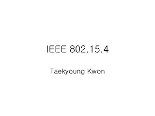
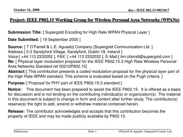
Project: IEEE P802.15 Working Group for Wireless Personal Area Networks (WPANs) Submission Title: [ Supergold Encoding for High Rate WPAN Physical Layer ] Date Submitted: [ 19 September 2000 ] Source: [ T O’Farrell & L.E. Aguado] Company [Supergold Communication Ltd. ] Address [ 2-3 Sandyford Village, Sandyford, Dublin 18, Ireland ] Voice:[ +44 113 2332052 ], FAX: [ +44 113 2332032 ], E-Mail:[ tim.ofarrell@supergold.com ] Re: [ Physical layer modulation proposal for the IEEE P802.15.3 High Rate Wireless Personal Area Networks Standard.ref 00210P802.15] Abstract: [ This contribution presents a coded modulation proposal for the physical layer part of the High Rate WPAN standard. This scheme is evaluated based on the Pugh criteria. ] Purpose: [ Proposal for PHY part of IEEE P802.15.3 standard.] Notice: This document has been prepared to assist the IEEE P802.15. It is offered as a basis for discussion and is not binding on the contributing individual(s) or organization(s). The material in this document is subject to change in form and content after further study. The contributor(s) reserve(s) the right to add, amend or withdraw material contained herein. Release: The contributor acknowledges and accepts that this contribution becomes the property of IEEE and may be made publicly available by P802.15. O'Farrell & Aguado, Supergold Comm. Ltd.
Supergold Communication • Supergold Communication is a campus start up company that specialises in solutions for wireless communications: • Sequence Coded Modulation • Sequence/Code Design • Synchronisation • By efficiently exploiting the distance properties of sequences/codes, Supergold’s solutions balance the trade-off between bandwidth efficiency, BER performance and complexity. • Supergold’s solutions can be beneficially applied in • WPAN • WLAN • Wireless Infrared • Cellular Mobile O'Farrell & Aguado, Supergold Comm. Ltd.
Sequence Coded Modulation for High Rate WPAN PHY • M-ary symbol modulation using QPSK chip modulation • near constant amplitude • 3 dB PA back-off and low power consumption • robust in multipath fading up to 30 ns rms delay spread • Single-error-correcting concatenated RS(127,125) code • RS code matched to M-ary modulation • very simple Berlekamp-Massey hard-decision decoding • very high rate code (0.98) • > 3 dB coding gain over QPSK @ 10-6 BER • High spectral efficiency: 21.53 Mbit/s data rate in 22MHz O'Farrell & Aguado, Supergold Comm. Ltd.
Properties of the sequence coded modulation (cont.) • Based on pre-existing technology • Feasible solution • Short Development time • Dual mode 802.15.1 / 802.15.3 using common RF blocks • Works in the 2.4 GHz ISM band with 802.11 channelisation • Uses a 12.5 Mchip/s chipping rate • Allows for 802.11b - 802.15.1 and 802.15.3 co-existence • Can operate in 5 GHz band • Very low baseband complexity • Uses Clear Channel Assessment (CCA) as in 802.11b O'Farrell & Aguado, Supergold Comm. Ltd.
Example of Link Budget for Two-Ray Model [based on: IEEE 802.15-00/050r1, Rick Roberts] Rx Noise Figure: 15 dB (inexpensive implementation) Rx Noise Bandwidth: 15.625 MHz Rx Noise Floor: -174+10*log(15.625*106)+15 -87 dBm Implementation Loss Margin: 6 dB Antenna Gain: 0 dB O'Farrell & Aguado, Supergold Comm. Ltd.
Example of Link Budget for Two-Ray Model (Cont.) Maximum Second Ray Delay: 25 ns Maximum Second Ray Refflection Coefficient: -6 dB Required Direct Ray Range: 10 m Loss Equation (dB): L = 32.5+20log(dmeters)+20log(FGHz) At 2.4 GHz, assuming the direct ray is blocked, the loss of the reflected ray path (17.4 m) is: L = 32.5+24.8+7.6+6 71dB (6 dB reflection coefficient) Including antenna gain and implementation loss: Total Loss Budget: L + 2x0 + 6 = 77 dB Rx Sensitivity is -75 dBm for an operating SNR of 10 dB at 10 -6 BER Tx Power: Noise Floor + SNR + Loss = -87 dBm + 10 dB + 77 dB Tx Power 0 dBm O'Farrell & Aguado, Supergold Comm. Ltd.
BPF 802.15.3 IF Filter SAW 50MHz Oscillator BPF Band Filter BPF 802.15.1 IF Filter ADC BB Processing AGC RSSI LPF ADC Rx I LNA IF Amp LPF ADC Rx Q MAC RF Synthesiser IF Synthesiser 0o / 90o LPF DAC Tx Q PA DAC LPF Tx I Image Reject Filter BPF PHY Functional Schematic O'Farrell & Aguado, Supergold Comm. Ltd.
8 xI Baseband Processor — M-ary Sequence Coded Modem I OUT Select1 of 128Sequences 1 7 c d RSEncoder DATA IN xQ 8 Q OUT 8 1 rI Rx I IN MaximumLikelyhoodDetector FastTransformCorrelator c’ 1 7 y RSDecoder DATAOUT 8 1 rQ Rx Q IN O'Farrell & Aguado, Supergold Comm. Ltd.
RF Functionality • All RF blocks shared between 802.15.1 and 802.15.3 modes. Except IF filters • Transmit power = 0 dBm • RFPA efficiency of 33%, 3 dB RFPA back-off • CMOS technology • BB Functionality • Fast transform correlators - 12.5 Mchips/s rate • 3-bit Rx ADCs - 50 Msample/s rate • 6-bit Tx DACs - 50 Msample/s rate • 6-bit AGC ADC • 16-tap digital raised-cosine pulse shaping filter • 30K gates for BB processing • 0.18u CMOS process in a dedicated ASIC • 1 chip implementation, 1 crystal, 4 filters (front-end, IF x 2, Tx IRF) O'Farrell & Aguado, Supergold Comm. Ltd.
Characteristic of pulse shape digital raised-cosine filter O'Farrell & Aguado, Supergold Comm. Ltd.
General Solution Criteria 2.1. Unit Manufacturing Cost Similar to 802.15.1 equivalent UMC at 2H 2000 • Similar architecture to IEEE 802.11b • Much simpler baseband processing than 802.11b (30K gates) • Low power PA (0 dBm Tx Power) • Shared RF architecture for 802.15.1 and 802.15.3 modes • 1 Chip RF / BB implementation + 5 external components O'Farrell & Aguado, Supergold Comm. Ltd.
General Solution Criteria 2.2. Signal Robustness 2.2.2. Interference and Susceptibility • BER criterion = 10-3 3dB loss of required sensitivity for: • J/S (MAI) = -6 dB co-channel • J/S (CW) = -7 dB co-channel • Adjacent+1 channel power attenuation > 50 dBc min. In-band interference protection > 40 dBc • Out-of-band attenuation > 80 dBc Complies with 802.15.1 out-of-band blocking O'Farrell & Aguado, Supergold Comm. Ltd.
General Solution Criteria 2.2.2. Interference and Susceptibility (cont.) System performance in the presence of interference O'Farrell & Aguado, Supergold Comm. Ltd.
General Solution Criteria 2.2.3. Intermodulation Resistance: IP3 Specification of RF Front-end Band Filter RF Mixer SAW IF Channel Filter LNA BPF BPF Gain (dB) -2 +15 +10 -10 IP3 (dBm) -4 +5 IP3TOTreferred to the input = -9 dBm O'Farrell & Aguado, Supergold Comm. Ltd.
General Solution Criteria 2.2.3. Intermodulation Resistance: Intermodulating signal -34 dBm IM S + 3 dB Freq MHz 2412 Ch1 2432 Ch5 2452 Ch9 2472 Ch13 Sensitivity S = -75 dB, C/I = 10 dB, Corr = 10log(103/10-1) = 0 dB, IP3 = -9 dBm IM3TOT = -85.8 dBm IM = [2.IP3 +(S - C/I +Corr)]/3 = -34 dBm The receiver can tolerate intermodulating signals of up to -34dBm whilst retaining a BER=10-6 with 3 dB Eb/N0 loss. Input IP2 = +16.6 dBm. O'Farrell & Aguado, Supergold Comm. Ltd.
General Solution Criteria 2.2.4. Jamming Resistance 1. Microwave oven interference: Interference bandwidth = 2450 to 2460 MHz. CCA would detect jammer and select clear channel.Two free channel are available from 3 non-over-lapping channels while three free channels are available from 4 overlapping channels. 2-3. 802.15.1 piconet 802.15.1 randomly hops over 78 1MHz-bands. 802.15.3 is jammed by hops into 15.625 MHz jamming sensitive area; jamming prob 15.625 / 78 20 %. 4. 802.15.3 transmitting MPG2-DVD DVD bit stream takes 30% of channel throughput. If 2 un-coordinated WPANs share the 1 channel with CCA-deferred access then >50% throughput expected. Otherwise CCA in subject WPAN would select clear channel. 5. 802.11a network Working on a disjoint frequency band no jamming. 6. 802.11b network CCA in subject WPAN would select clear channel. O'Farrell & Aguado, Supergold Comm. Ltd.
General Solution Criteria • 2.2.5. Multiple Access • 21.53 Mbit/s bit rate Throughput in [15, 20] Mbit/s range. • Coordinated time-multiplexing used for multiple access to shared channel. • No constraint when multiplexing an MPEG2 stream (4.5 Mbit/s) with 512-byte asynchronous packets (max. 273s). • CASE 1: three MPEG2 streams (at 4.5Mbit/s) share the total throughput (min.) 15 Mbit/s. • CASE 2 and 3: one MPEG2 stream takes 4.5 Mbit/s whilst the asynchronous services share the remaining throughput in a time-multiplexing manner. O'Farrell & Aguado, Supergold Comm. Ltd.
Physical Layout 802.15.3 A2 A1 < 0.5 m 802.15.1 B1 B2 3m 3m x m General Solution Criteria 2.2.6. Coexistence 802.15.1 piconet scenario: IC1 & IC2: x = 7 m IC3: x = 97 m IC4 & IC5: x = 47 m O'Farrell & Aguado, Supergold Comm. Ltd.
General Solution Criteria 2.2.6. Coexistence cont. 802.15.1 Devices Tx at 1 mW A1 will interfere with B1 but not B2 while A2 will interfere with B1 and B2. B1 Rx - A1 Tx Pwr = 0 dBm; Pahtloss(A1-B1) ~ 50 dB; Rx Pwr at B1 due to A1 ~ -50 dBm in 15.625 MHz channel bandwidth; i.e. a power density of -61.5 dBm/MHz - A2 interferes with B1 in the same manner as A1 - B2 Tx Pwr = 0 dBm; Pathloss(B2-B1) ~ 60dB; Rx Pwr at B1 due to B2 ~ -60 dBm C/I ~ -60 - (-50 +3) ~ -13 dB , B1 jams when signals collide B2 Rx - A1 Tx Pwr = 0 dBm; Pahtloss(A1-B2) ~ 62.4 dB; Rx Pwr at B2 due to A1 ~ -62.4 dBm in 15.625 MHz channel bandwidth; i.e. a power density of -74.3 dBm/MHz - A2 Tx Pwr = 0 dBm; Pahtloss(A2-B2) ~ 57 dB; Rx Pwr at B2 due to A2 ~ -57 dBm in 15.625 MHz channel bandwidth; i.e. a power density of -69 dBm/MHz - B1 Tx Pwr = 0 dBm; Pathloss(B1-B2) ~ 60dB; Rx Pwr at B2 due to B1 ~ -60 dBm C/I ~ -60 - 10log(10-6.9+10-7.43) ~ 7.9 dB , B2 jams when signals collide O'Farrell & Aguado, Supergold Comm. Ltd.
General Solution Criteria 2.2.6. Coexistence cont. 802.15.1 Devices Tx at 100 mW Neither A1 nor A2 will not interfere with either B1 or B2 B1 Rx - A1 Tx Pwr = 0 dBm; Pahtloss(A1-B1) ~ 50 dB; Rx Pwr at B1 due to A1 ~ -50 dBm in 15.625 MHz channel bandwidth; i.e. a power density of -61.5 dBm/MHz - A2 interferes with B1 in the same manner as A1 - B2 Tx Pwr = 20 dBm; Pathloss(B2-B1) ~ 60dB; Rx Pwr at B1 due to B2 ~ -40 dBm C/I ~ -40 - (-61.5 +3) ~ 18.5 dB , B1 does not jam when signals collide B2 Rx - A1 Tx Pwr = 0 dBm; Pahtloss(A1-B2) ~ 62.4 dB; Rx Pwr at B2 due to A1 ~ -62.4 dBm in 15.625 MHz channel bandwidth; i.e. a power density of -74.3 dBm/MHz - A2 Tx Pwr = 0 dBm; Pahtloss(A2-B2) ~ 57 dB; Rx Pwr at B2 due to A2 ~ -57 dBm in 15.625 MHz channel bandwidth; i.e. a power density of -69 dBm/MHz - B1 Tx Pwr = 20 dBm; Pathloss(B1-B2) ~ 60dB; Rx Pwr at B2 due to B1 ~ -40 dBm C/I ~ -40 - 10log(10-6.9+10-7.43) ~ 27.9 dB , B2 does not jam when signals collide O'Farrell & Aguado, Supergold Comm. Ltd.
General Solution Criteria 2.2.6. Coexistence cont. IC1 & IC2 - 802.15.1 network at 0 dBm Tx Power Probability of 802.15.1 hopping into 802.15.3 15.625 MHz channel is P(interf.) = 15.625 / 78 = 20% 802.15.1 throughput over 80 % IC1 & IC2 - 802.15.1 network at 20 dBm Tx Power As neither device is jammed the throughput is always 100 % IC3 & IC5 - 802.11b network: Different channels would be selected for each network via CCA IC4 - 802.11a network 802.15.3 and 802.11a use different frequency bands and would be able to co-exist without interfering with each other. O'Farrell & Aguado, Supergold Comm. Ltd.
General Solution Criteria • 2.3. Interoperability • The 802.15.3 WPAN implements a dual mode radio with shared RF blocks for interoperability with 802.15.1. • Rx shared components include band filter, LNA, RF mixer and synthesiser, IF amplifier, IF mixer and synthesiser, anti-aliasing filters, ADCs and baseband processing unit. • Tx shared components include band filter, PA, RF mixer and Synthesiser, image rejection filter, IF mixer and synthesiser, smoothing filters, DACs and baseband processing unit. • A dedicated IF channel filter matched to the 802.25.1 channel bandwidth is required in addition to the 802.11.3 IF channel filter. O'Farrell & Aguado, Supergold Comm. Ltd.
General Solution Criteria 2.4. Technical Feasibility 2.4.1. Manufactureability • System architecture utilises pre-existing 802.11b and 802.15.1 technology. • Baseband processing functionality similar to existing solutions such as MBOK and CCK. 2.4.2. Time to Market • Pre-existence of technology will ensure short development cycle • Only PHY part proposed • Available earlier than 1Q2002 O'Farrell & Aguado, Supergold Comm. Ltd.
General Solution Criteria 2.4.3. Regulatory Impact • The proposed scheme is compliant with regulatory standards FCC(25.249), ETSI 300-328 and ARIB STD-T66. 2.4.4. Maturity of Solution • The system utilises existing 802.11b and 802.15.1 technology • Underlying modulation is constant amplitude QPSK • Baseband processing less complicated than CCK • Baseband scheme tested in a general purpose hardware demonstrator O'Farrell & Aguado, Supergold Comm. Ltd.
General Solution Criteria 2.5. Scalability 2.5.1.1. Power Consumption • Transmit power can be changed with impact on either range or throughput (through change in coding rate). 2.5.1.2. Data Rate • Coding level can be adjusted to fit power and channel conditions. 2.5.1.3. Frequency Band of Operation • This modulation scheme can be applied at both 2.4 GHz and 5 GHz 2.5.1.4. Cost • Changing the level of coding or power would not significantly affect the unit cost. 2.5.1.5. Function • Equalisation can be introduced into the scheme inorder to enhance resistance to time dispersive channels with large delay spreads. O'Farrell & Aguado, Supergold Comm. Ltd.
PHY Layer Criteria 4.1. Size and Form Factor • Dual mode RF / BB parts integrated in one PHY chip. • Five external components: crystal oscillator, band filter, 802.15.1 IF filter, 802.15.3 SAW IF filter, Tx image rejection filter. • One chip for dual mode 802.15.1 / 802.15.3 MAC. • 0.18 CMOS process • Size smaller than a Compact Flash Type 1 card. O'Farrell & Aguado, Supergold Comm. Ltd.
PHY Layer Criteria 4.2. MAC/PHY Throughput 4.2.1. Minimum MAC/PHY Throughput • Offered data rate = 2 x 12.5x106 x (7/8) x (125/127) = 21.531 Mbit/s • PHY overhead due to coding = 1 - (7/8 x 125/127) = 13.88% • minimum MAC/PHY throughput is met for services that use a MAC overhead of less than or equal to 8% 4.2.2. High End MAC/PHY Throughput • One throughput level is offered O'Farrell & Aguado, Supergold Comm. Ltd.
PHY Layer Criteria 4.2. MAC/PHY Throughput cont. PLCP Packet Format PPDU PLCP Preamble PLCP Header Signal 8 bits Service 8 bits Length 16 bits CRC 16 bits SFD 16 bits PSDU Sync 2*64 chips T1 T2 T3 2*12.5 Mchip/s QPSK 21.531 Mb/s QPSK 21.531 Mb/s QPSK T1 = 128/25000000 = 5.12 us T2 = 16/21531000 = 0.74 us T3 = 48/215310000 = 2.23 us O'Farrell & Aguado, Supergold Comm. Ltd.
PHY Layer Criteria 4.2. MAC/PHY Throughput cont. PLCP Packet Parameters PLCP Preamble: = T1 + T2 = 5.12 + 0.74 = 5.86 us PLCP Header: = T3 = 2.23 us aSIFSTIME: = 10.00 us aslotTIME: = 20.00 us O'Farrell & Aguado, Supergold Comm. Ltd.
PHY Layer Criteria 4.3. Frequency Band • This proposal is aimed at the 2.4 GHz ISM band, but is also applicable to the 5GHz ISM band. 4.4. Number of Simultaneously Operating Full Throughput PANs • The IEEE 802.11b channelisation is adopted which provides for 14 overlapping channels • With non-overlapping channels, up to 3 co-located networks can share the 2.4 GHz ISM band without co-channel interference, (3 non-overlapping 25 MHz channels , fc= 2412, 2437, 2462 MHz). • With overlapping channels, up to 4 co-located networks can share the 2.4 GHz ISM band without significant co-channel interference, (4 overlapping 20 MHz channels, fc = 2412, 2432, 2452, 2472M Hz). • Up to 5 co-located networks could share the 5 GHz ISM band with no co-channel interference O'Farrell & Aguado, Supergold Comm. Ltd.
PHY Layer Criteria 4.4. Cont. B1 802.15.3 2.412 GHz 1m Physical Layout 802.15.3 2.432 GHz A2 A1 802.15.3 2.432 GHz 10m 1m B2 802.15.3 2.452 GHz - A1 Tx Pwr = 0dBm; Pahtloss(A1-A2) ~60 dB; - Pathloss(B1-A2) ~ 40 dB and Pathloss(B2-A2) ~ 40 dB (avoids IM3 effects) - For 20 MHz channel separation the adjacent channel interference (ACI) produced by the filtered signals at 1 m is 3+ACI(0m) - pathloss(1m) 3 - 89 - 40 = -126 dBm - As the receiver sensitivity is -75 dBm, then the C/I margin is at least 50 dB - Hence there is no significant impact on throughput due to ACI nor associated IM3. • 4.6. Range • For 0 dBm Tx. Power, range > 10 m (for link budget presented) O'Farrell & Aguado, Supergold Comm. Ltd.
PHY Layer Criteria 4.7. Sensitivity BER v. Eb/N0 Performance in the AWGN channel O'Farrell & Aguado, Supergold Comm. Ltd.
PHY Layer Criteria 4.7. Sensitivity BER v. SNR Performance in the AWGN channel O'Farrell & Aguado, Supergold Comm. Ltd.
PHY Layer Criteria 4.7. Sensitivity PER v. SNR Performance in the AWGN channel O'Farrell & Aguado, Supergold Comm. Ltd.
PHY Layer Criteria 4.8.2. Delay Spread Tolerance System Performance in the multipath channel for TRMS = 25 ns O'Farrell & Aguado, Supergold Comm. Ltd.
PHY Layer Criteria 4.8.2. Delay Spread Tolerance • The BER criterion = 10-3 is met for TRMS = 25 ns with no equalisation • A delay spread of 30ns is tolerated for more than 90% of the channels with FER < 1% at Eb/N0 = 17.5 dB • No equalisation required O'Farrell & Aguado, Supergold Comm. Ltd.
PHY Layer Criteria 4.9. Power Consumption • 0 dBm transmitted power • QPSK: near constant amplitude and 3 dB RFPA back-off. • Low baseband processor complexity • low complexity fast transform correlation detection and FEC • no equaliser • 30k BB processing gate count • Dedicated ASIC using 0.18 u CMOS process PHY peak power consumption is 330 mW excluding MAC. O'Farrell & Aguado, Supergold Comm. Ltd.
4.9. Power Consumption Budget in mW for 0.18 u Technology Transmitter PA (33% eff, 3dB back-off) 10* RF up-mixer 30 RF Synthesiser 25 IF up-mixer 20 IF Synthesiser 15 Smoothing Filters (I&Q) 10 DACs (I&Q) 40 BB Processing (ASIC) 125 * 2dB band filter loss Tx Total 275 Receiver LNA 10 RF down-mixer 30 RF Synthesiser 25 IF Amp 10 IF down-mixer 20 IF Synthesiser 15 Anti-aliasing Filters (I&Q) 10 ADCs (I&Q) 40 ADC (RSSI) 20 BB Processing (ASIC) 150 Rx Total 330 O'Farrell & Aguado, Supergold Comm. Ltd.
Pugh Matrix - General Solution Criteria O'Farrell & Aguado, Supergold Comm. Ltd.
Pugh Matrix - General Solution Criteria O'Farrell & Aguado, Supergold Comm. Ltd.
Pugh Matrix - PHY Layer Criteria O'Farrell & Aguado, Supergold Comm. Ltd.
Pugh Matrix - PHY Layer Criteria O'Farrell & Aguado, Supergold Comm. Ltd.