Download
1 / 7

E N D
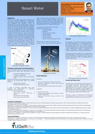
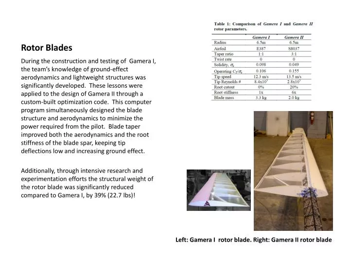
Rotor Blades During the construction and testing of Gamera I, the team’s knowledge of ground-effect aerodynamics and lightweight structures was significantly developed. These lessons were applied to the design of Gamera II through a custom-built optimization code. This computer program simultaneously designed the blade structure and aerodynamics to minimize the power required from the pilot. Blade taper improved both the aerodynamics and the root stiffness of the blade spar, keeping tip deflections low and increasing ground effect. Additionally, through intensive research and experimentation efforts the structural weight of the rotor blade was significantly reduced compared to Gamera I, by 39% (22.7 lbs)! Left: Gamera I rotor blade. Right: Gamera II rotor blade
Gamera II Gamera I Blade tip: less structure where you don’t need it Blade root: more structure where you do need it
Result of the Gamera II aero-structural optimization trade studies. These results show the effect of radius, structural technologies, and manufacturing complexity. The Gamera I and Gamera II design points are highlighted. Power required is shown for rotor height of 60 cm (2 ft) above the ground. The 60-second duration flights will be flown as close to the ground as possible to increase ground effect advantages.
Optimization Design Variables At each blade section vary… Spar cap sizes Airfoil Chord (Restricted to bi-linear taper) Tip speed (RPM) Root cutout Rotor radius
Human Power The heart of Gamera II is the human pilot. As the aircraft’s engine and accounting for 2/3 of the total vehicle weight, the human component needs as much or more engineering focus than other vehicle parts. Gamera I made use of hand cranks to boost power output in the 15-20 second flight range. The Gamera II goal was longer flight durations, on the order of 60 seconds, so the team conducted more testing on the addition of hand cranks to validate this design choice. Using a commercial exercise machine that includes both leg and arm motion, comprehensive experiments were performed on test pilots. The results confirmed a power benefit, up to 20% for a 60-second effort, by using hand cranks in addition to the typical leg cranks. A recruitment effort resulted in three test pilots for Gamera II. They are all in the same weight range of 135-145 lbs and have excellent power to weight ratios (W/kg). And all are scientists or engineers at the University of Maryland! Test pilot Kyle Gluesenkamp on the SCIFIT Pro2 Total Body Recumbent Bike machine. Initial pilot power test results showing that adding hand cranks and engaging the upper body results in increased power output for the short flight durations of interest.
Airframe Truss Arms One downside of the quad-rotor design is the need for large airframe support arms that connect the rotors and cockpit. These airframe truss arms need to react large bending moments but be as lightweight as possible. For Gamera II, innovative micro-truss structures were employed to greatly reduce airframe weight. Originally developed for Gamera I, an even lighter version was designed for Gamera II, and more extensively employed. The result was a 39% reduction in weight over Gamera I, an incredible 12.5 lbs! Gamera II airframe truss arm design “Heavy” (left) and “Light” (right) micro-truss structures. Compression testing micro-truss structures Comparison of buckling efficiency between commercially available carbon fiber tubes and micro-truss technology.
Static tested to 120% design load • Projected weight: 2.2 kg [4.8 lb] • As built weight: 2.1 kg [4.6 lb]