Download
1 / 15
150 likes | 267 Views
COMMON RULES ON OPERATION MODES. RUN MODE: the board does what is needed to make SVT run only status reading and error bit clearing is allowed from VME

E N D
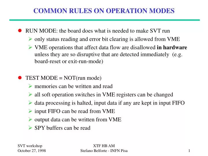
COMMON RULES ON OPERATION MODES • RUN MODE: the board does what is needed to make SVT run • only status reading and error bit clearing is allowed from VME • VME operations that affect data flow are disallowed in hardware unless they are so disruptive that are detected immediately (e.g. board-reset or exit-run-mode) • TEST MODE = NOT(run mode) • memories can be written and read • all soft operation switches in VME registers can be changed • data processing is halted, input data if any are kept in input FIFO • input FIFO can be read from VME • output data can be written from VME • SPY buffers can be read XTF HB AM Stefano Belforte - INFN Pisa
XTF (XTRP Fanout) board • There is only one XTF in SVT • XTF receives tracks from XTRP, 21 bit per track • XTRP info fills completely one SVT word • XTF sends tracks to the 12 SVT phi-slices. • Each slice only receives the tracks it is interested on (programmable feature) • XTF makes two words out of each XTRP track • 1. What is needed for AM • 2. What is needed for Track Fitter XTF HB AM Stefano Belforte - INFN Pisa
XTF functions • Input packet • Output packet: • for AM use all XTRP 21 bits as input to LUT to get 12-bit SuperStrip data, and add Layer=5 to tag word. Another 21-in /12-out LUT defines which phi wedge to send a given road • to Track Fitter send the original XTRP data • Read/write LUT’s by VME • Input data are logged in Spy Buffer • Reformatted data and list of enabled wedges logged in Spy Buffer • But: Will not have 12 independent Spy Buffers on outputs XTF HB AM Stefano Belforte - INFN Pisa
XTF block diagram One input stream XTRP word FIFO SPY BUFFER LUT LUT Output Enables SPY BUFFER TF word AM word 12 FAN OUT 12 output streams XTF HB AM Stefano Belforte - INFN Pisa
XTF (poor) artist’s view: 3 slots, 1 VME i/f VME XTRP to MRG’s XTF HB AM Stefano Belforte - INFN Pisa
Errors Detected by the XTF • Communication error with XTRP • Parity Error • Fifo Overflow • Invalid Data XTF HB AM Stefano Belforte - INFN Pisa
XTF performance • XTF is not critical: all XTRP tracks will be long arrived before SVXII hits even start coming, as long as they are all received before the last SVX hit, there is no delay • We never timed XTF processing • XTF does not need to run fast • 50nsec clock is likely more then adequate • this means one XTRP track is sent to AM each 100nsec • 2 sec after L1A (when SVX readout starts) up to 20 XTRP tracks have been sent to AM XTF HB AM Stefano Belforte - INFN Pisa
Associative Memory Board (AMB) • Only communicates with AMS for operation and with VME for initial setup at power on. • No error diagnostics, no Spy Buffers. • It has the same functionality as one AM chip, just larger • some delay as data travel up/down the glue tree • You only need to know how Associative Memory chips work: • AM built around a detector with 6 layers, 12 bit of data each layer • one layer is special (XTRP) must be always present(could be turned off if desired) • 5 layers can be used for SVX (only 4 for TDR studies) • 3-bit layer + 12-bit data = 15-bit SuperStrip (basic concept!) XTF HB AM Stefano Belforte - INFN Pisa
SuperStrips (SS) • SuperStrip = hit or track at reduced resolution • AM works on 15-bit SuperStrips • Hit, track SuperStrip via LUT (different map in each layer) • XTRP track (21 bits): max flexibility, use all info to find SS. • SVX hits (21 bits including layer): drop 4 bits (3-0), then use 17 x 15 bit LUT. Layer number can be different in hit and SuperStrip (but no plan to use this feature). • SVX SuperStrip width must be a a multiple of 16 times the HF precision (1/16th of the pitch)SuperStrip width must be a multiple of silicon pitch (which is in general different in each layer) XTF HB AM Stefano Belforte - INFN Pisa
AM algorithm • PATTERN: one SuperStrip for each Layer, stored from VME • AM looks at hits as they are read out, matches are recorded by each pattern: 1 MATCH BIT per Layer • After EndEvent, matches are counted in all patterns in parallel. There is one counter for each pattern, acted upon by 6 Opcodes sent in series, one for each layer (1st acts on layer 5, 2nd on layer 4 . . .) • 2 options: COUNT increments counter if layer had a match SHIFT increments counter anyhow • When counter reaches 6, pattern is queued for output • Counters can be cleared and a new series of Count/Shift performed. • Output of pattern can be done at any time, even in between Count/Shift (but not in parallel) XTF HB AM Stefano Belforte - INFN Pisa
AMB performance • AMB can run at 30 32 MHz (maybe more) • some concerns about power and cooling • within SVT AMB runs at exactly same clock as AM • receives one hit each clock cycle • sends one road each 3 clock cycles • 33 clock cycles between the last hit and the first road • Timing of all SVT on realistic data using SVTSIM in progress XTF HB AM Stefano Belforte - INFN Pisa
Hit Buffer (HB) board • There is one HB for each phi wedge, 12 total • HIT is generic name: SVX hits + XTRP tracks • Receives hits and stores in Hit List Memory (HLM) • Hit List Memory is 64K words, 21 bits each. • allocate fixed number of words (2 or 4 or 8) to each SuperStrip in each Layer (e.g. 4 SVX hits, 1 XTRP track). Excess data is lost. • Hit List Memory = Data Base keyed by SuperStrip • Maps hits SuperStrips via VME-loaded LUT. • LUT also defines the number of words in HLM for each SS • Receives roads and sends out hits belonging to each road • Loops on layers with internal counter • Maps layer,road SuperStrip via VME-loaded LUT • Stores input & output in Spy Buffers XTF HB AM Stefano Belforte - INFN Pisa
HB running options • Mapping from hits and roads is fully configurable via VME • Operation mode is almost completely fixed: • Maximum number of layers (up to 8) set via dip switch • Hold from output stream can be ignored via dip switch,allows to run HB with no board downstream for test XTF HB AM Stefano Belforte - INFN Pisa
Errors Detected by the HB • Communication error with upstream Merger (sends hits) • Parity Error • Fifo Overflow • Invalid Data • Communication error with AMS (sends roads) • Parity Error • Fifo Overflow • Invalid Data • Input mismatch between roads and hits • Lost Sync • Hit List Memory overflow in at least one SuperStrip • Internal Overflow XTF HB AM Stefano Belforte - INFN Pisa
HB performance • HB has the most time demanding task per clock cycle • SVT is a pipeline, one word is processed each clock cycle • When writing hits in Hit List Memory address depends on how many hits arrived already for a given SuperStripRead - Modify - Write in one clock cycle: internal Hit List Memory counters (cache tag RAM) runs at double clock speed • HB runs at slowish clock frequency: 25 ~ 28 MHz • Still should have handled all hits by the time AM roads arrive • Sending information to TF: • one AM road produces one multi-word packet: • all hits (4 SVX + 2 XTRP words min) • the road itself • total 300nsec (more if more hits in some SS) • Timing of all SVT on realistic data using SVTSIM in progress XTF HB AM Stefano Belforte - INFN Pisa