Download
1 / 88
890 likes | 937 Views
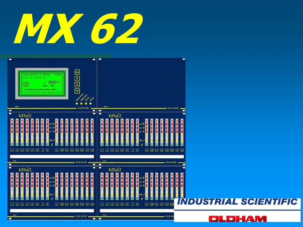
MX 62. MX 62 System. SIL 3 Notified by EXAM N° BVS Pb 04/06X. Full redundant system (SIL 3) Up to 64 digital or analog transmitters Up to 128 addressable relays Up to 64 programmable analog outputs

E N D
MX 62 System SIL 3 Notified by EXAM N° BVS Pb 04/06X • Full redundant system (SIL 3) • Up to 64 digital or analog transmitters • Up to 128 addressable relays • Up to 64 programmable analog outputs • MX62 is not only a gas controller but a truly PLC dedicated to gas detection
MX 62 System • The gas and flame control unit MX 62 enables: • to set up complex and elaborated installations. • to increase the availability of the system:SIL3 approved according to EN50402 • reduction of the material and wiring costs and of the whole equipment • to ensure supervisions .
MX 62 Fonctionning safety of gas detection fixed systems
10m Control units X Control unit X Schema 2 Schema 1 6m 13m 20m Estimated length for the wiring of the whole installation: 975m or a 1300 euros cost Estimated length for the wiring of the whole installation: 466m or a 620 euros cost 10m Installation avec centrale autre que MX62 60m 13m 40m 15m 12m 20m 30m Schema 2bis 30m Schema 1bis MX62 MX62 Estimated length for the wiring of the whole installation: 200m or a 265 euros cost Estimated length for the wiring of the whole installation: 151m or a 200 euros cost installtion avec centrale MX62 60m 60m 60m 30m 30m Legend: Looped Input Remote Module transmitter Delimitation of high-risk zone under surveillance Delimitation of an industrial site Network splitter Cable: type U1000RVFV 8F70 per metre Control unit without MX 62 with MX 62
MX 62 into detail • Power supplies • control module • Local or remote modules • LED modules • Display modules • Relay modules • Analog output modules • Softwares and interfaces • Housing.
POWER SUPPLY BLOCK • The power supply block and its accessories (protections, switches, terminals) will be fixed in the housing • The power supply block will depend on the choice of the equipment: 13W maximum per channel 240 to 1500W
CONTROLLER MODULE(CPU):CM It is the control unit of the MX62. Two synchronised 16 bits micro-controllers run in parallel. They redundantly and permanently compare measurements and status of transmitters to initiate all necessary alarms. The u.c.enables the connection to PC/PLC, different modules and MMC uploading.
No fault µC A inputs outputs µC B WARNING !!! The info received and exchanged between both processors are different µC A inputs outputs µC B Status of the controller :How does the MX 62 react in case of single fault. SIL 2 or SIL 3 applications System in normal operation. LOSS of one SIL LEVEL but the system is still safe .
controller A CPU (controller module) controller B MX 62 and transmitters( max 64) With remote modules: LPM Flat cables Flat cables or twisted wires With local modules: AIM
digital addressable transmitters addressable transmitters via a safety MODBUS ASCII communication Wheatstone bridge detectors Wheatstone bridge detectors via an MX 62 can be connected with : transmitters 4..20mA transmitters 4..20mA all types of ( 2 or 3 wires )
Analog input module Analog input module Analog input module + RS485 + RS485 + RS485 transmitters 4..20 mA transmitters 4..20 mA transmitters 4..20 mA (service) (service) (service) Module I Module II Module VIII controller A : : : controller B 8 addressable modules AIM fitted with 8 inputs CPU 0,5m
Analog Input Modules:connections 24v = transmitter power suppl GND = ground Sig. = signal 4-20mA from the transmitter A = line A of RS 485 network B = line B of RS 485 network
(power supply + signal) Analog Input Modules AIM Transmitter ( 3 wires ) (loop/4 to 20mA) Transmitter ( 2 wires ) Site
Site 3- wires (power supply + signal) And 2 additional wires for RS485 Remote Transmitter programming/calibration
+ RS485 4..20mA analog. 4..20mA analog. (service) controller A Module VIII controller B « CATALYTIC DETECTOR/ 4-20mA » ADAPTER MODULE WB interface (filaments / 4-20mA) CPU catalytic detector
CPU Maximal configuration: 8 analog input modules (8 transmitters max.. per module) 64 transmitters in total Analog Input Modules 4-20mA transmitters Flat cable 8 wires nota: the connected module with one transmitter is considered by the control unit to be fitted with 8 transmitters. Back housing of a control unit MX62
+24V GND mA A B AIM: special version Smoke detector Smoke detector Smoke detector +2VCC RFL mA maximum 32 detectors Curent limitor module (20 mA)
Adapter Module LPM for digital and analog transmitters controller A Adapter module For numeric or/and Analog transmitters connections : controller B Adapter module For numeric or/and Analog transmittes connections CPU 1,6 km max • - up to 4 remote/addressable modules • (16 addresses per loop) • adress module :1/3/5/7
Section 2 loop Section 1 ex: 16 adresses, lenght of loop=1.2 Kms* < 1.2 Kms * with tox. capt Ø 380mor 6 up to 24 ha power supply+network -(2x0,75mm²)+1p 0.32 mm²-
( 5 wires per captor ) AEM adapter module < 1.2 Kms alim locale Local power supply Mx62
Control room where the MX62 is: Capteur CPU Back housing of a control unit MX62 Building A Short connection Maximal configuration: 4 adapter modules 64 transmitters Building B The ADAPTER MODULES note: the connected module with one transmitter is considered by the control unit to be fitted with 8 transmitters. 2 3 1 4
LED MODULES :LEDM A group of 8 LED front panel per card. 16 channels front panels (3U-1/2 19 in)
Channel LED front panel Over scale alarme 3 alarme 2 alarme 1 Under scale (too negative) Failure ON/OFF Manual proper measurement displayed on LCD panel module and alarm reset Alarms are entirely and independently programmable
controller A controller B «LED» front panels LED front panels can be remote from the CPU. CPU RS 485
LCDM Module Escape key up key down key validation key Clear messages Service informations
LCD Module • The display clearly indicates: • the measurements and the units • the kind of gas and the scale of measurement • the alarms • the identification of the visual transmitter • the information for maintenance • Allows the printing gestionetc...
LCD Module • The display can be programmed differently: • no display • cyclic display of the channels • display on channel where an alarm is triggered • cyclic display on channels where alarms are triggered • manual display
4 LED for service informations : • System failure: system completely out of order • Single mode: redundancy is disrupted • Service: maintenance positions currently used • Battery: power cuts but saved by batteries…
LCD module: LCDM • In option memorizesdata and events that can be saved on PC thanks to the use of a communication module (2X RS485) • fitted with a memory 16Mb = capacity of 5 days • fitted with a memory 256Mb = capacity of 3 months • The « histogram » function(FIFO mode) is saved by a lithium battery.
Local and Remote LCD Modules • Remote • without LED • without indications • Oldham ’s logo • indication of measurement under alarm condition LOCAL
LCD module:installations • The display module can be directly fixed in the housing… • … or remote from the housing thanks to a network RS485:30 *LCD modules max. • Important: the first display module will be the master and others will be slaves (keypad deactivated). • Note: without remote LED modules...
600mm 800mm 2m LCD, LED panels system’s representation . CPU Distant zone n°2 Example: control room unit n°2 Distant zone n°1 Example: control room of the unit n°1
MX 62 REMOTE OUTPUT MODULES
Remote and addressable relay module : controller A Remote and addressable relay module controller B REMOTE RELAY MODULES:RM 1 km RS485 CPU 8 modules MAX.
RELAY MODULE RM • A relay module can be fitted with 1 or 2 cards: • a basicrelay module RBMfittedwith 8 relays and can be extended... • … a 2nd extensioncard REMfittedwith 8 other relays . • Adress 1 to 8 for each module(rotative switch)
Relay Module: RM • with8 modulesfitted with 16 relays: up to 128addressable relayscan beused • Independent and programmable relays can be piloted by FUNCTIONSdefined by the user: alarm type,acknowledgement mode,failures,logics states etc….