Download
1 / 38
390 likes | 551 Views
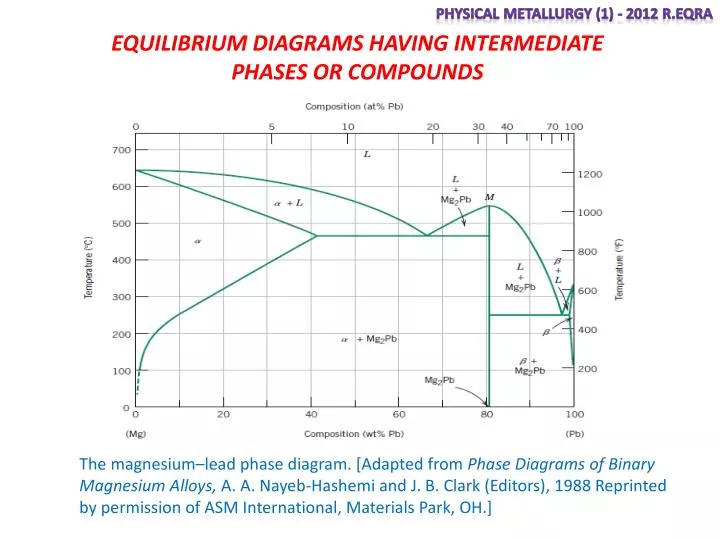
Physical Metallurgy (1) - 2012 R.Eqra. EQUILIBRIUM DIAGRAMS HAVING INTERMEDIATE PHASES OR COMPOUNDS.

E N D
Physical Metallurgy (1) - 2012 R.Eqra EQUILIBRIUM DIAGRAMS HAVING INTERMEDIATE PHASES OR COMPOUNDS The magnesium–lead phase diagram. [Adapted from Phase Diagrams of Binary Magnesium Alloys, A. A. Nayeb-Hashemi and J. B. Clark (Editors), 1988 Reprinted by permission of ASM International, Materials Park, OH.]
Physical Metallurgy (1) - 2012 R.Eqra PERITECTIC REACTIONS cooling Liquid + Solid1 Solid2 Heating Therefore,this is an example of an incongruent-melting intermediate alloy
Physical Metallurgy (1) - 2012 R.Eqra Alloy 1, 90A-10B, remains liquid until the liquidus line is reached at T1. Solidification now takes place by forming crystals of the pure metal A. As the temperature falls, the liquid is decreasing in amount, and its composition is moving down along the liquid us line. Let us examine the conditions that exist just above the peritectic temperature Tp
Physical Metallurgy (1) - 2012 R.Eqra The liquid contains 60A, while AmBncontains 70A. The liquid is not rich enough in A to form the compound by itself. The liquid must therefore react with just the right amount of solid A, in this case 8 percent, to bring its composition to that of the compound AmBn. The following reaction must have taken place at the peritectictemperature
Physical Metallurgy (1) - 2012 R.Eqra The reaction takes place all around the surface of each grain of solid A where the liquid touches it. When the correct composition is reached,thelayer solidifies into AmBnmaterial surrounding every grain of A. Further reaction is slow since it must wait for the diffusion of atoms through the peritecticwall of AmBnin order to continue (see Fig. 6·40). When diffusion is completed, all the liquid will have been consumed, and since only 8 percentof pure A was required for the reaction, there will be 67 percent of A left. The final microstructure will show grains of primary A surrounded by the compound AmBn
Physical Metallurgy (1) - 2012 R.Eqra Since there was 87.5 percent liquid before the reaction and 50 percentliquid after the reaction, it is apparent that 37.5 percent of the liquid reacted with 12.5 percentof solid A to give 50 percent of the compound AmBnat the peritectictemperature
Physical Metallurgy (1) - 2012 R.Eqra As cooling continues, the liquid now separates crystals of AmBn. The liquid becomes richer in B, and its composition gradually moves down and to the right along the liquidus line until it reaches point E, the eutectic temperature. At this temperature, there is only 5/50 x 100 or 10 percent liquid left. Since the liquid has reached the eutectic point, it now solidifies into the eutectic mixture of AmBn+ B. This alloy, at room temperature, will consist of 90 percent primary or proeutecticAmBnsurrounded by 10 percent of the eutectic (AmBn+ B) mixture. Figure 6-42 shows the cooling curve and the changes in microstructure at various points in the slow cooling of this alloy.
β Ag α pt Physical Metallurgy (1) - 2012 R.Eqra
Physical Metallurgy (1) - 2012 R.Eqra Two liquids partly soluble in the liquid state Monotectic reaction
Physical Metallurgy (1) - 2012 R.Eqra Two metal insoluble in the liquid and solid states
Physical Metallurgy (1) - 2012 R.Eqra Transformation in the solid state Allotropy
Physical Metallurgy (1) - 2012 R.Eqra Order – disorder transformation
Physical Metallurgy (1) - 2012 R.Eqra The eutectoid reaction
Physical Metallurgy (1) - 2012 R.Eqra The peritectoid reaction
Physical Metallurgy (1) - 2012 R.Eqra A region of the copper–zinc phase diagram that has been enlarged to show eutectoid and peritectic invariant points, labeled E (560C, 74 wt% Zn) and P (598C, 78.6 wt% Zn), respectively. [Adapted from Binary Alloy Phase Diagrams, 2nd edition, Vol. 2, T. B. Massalski (Editor-in-Chief), 1990. Reprinted by permission of ASM International, Materials Park, OH.] Eutectoid reaction Peritectic reaction
Physical Metallurgy (1) - 2012 R.Eqra A portion of the nickel–titanium phase diagram on which is shown a congruent melting point for the - phase solid solution at 1310C and 44.9 wt% Ti. [Adapted from Phase Diagrams of Binary Nickel Alloys, P. Nash (Editor), 1991. Reprinted by permission of ASM International, Materials Park, OH.]
Physical Metallurgy (1) - 2012 R.Eqra Figure 11-5 A hypothetical phase diagram
Physical Metallurgy (1) - 2012 R.Eqra Considerations for effective dispersion strengthening: (a) The precipitate phase should be hard and discontinuous, while the matrix should be continuous and soft, (b) the dispersed phase particles should be small and numerous, (c) the dispersed phase particles should be round ratherthan needle-like, and (d) larger amounts of the dispersed phase increase strengthening.
Physical Metallurgy (1) - 2012 R.Eqra Phase Rule Josiah Willard Gibbs (1839–1903) was a brilliant American physicist and mathematician who conducted some of the most important pioneering work related to thermodynamic equilibrium Gibbs developed the phase rule in 1875–1876. It describes the relationship between the number of components and the number of phases for a given system and the conditions that may be allowed to change (e.g., temperature , pressure, etc.). It has the general form: C is the number of chemically independent components, usually elements or compounds, in the system; F is the number of degrees of freedom, or the number of variables (such as temperature, pressure, or composition), that are allowed to change independently without changing the number of phases in equilibrium; and P is the number of phases present (please do not confuse P with “pressure”).
Physical Metallurgy (1) - 2012 R.Eqra Unary system at point A at point B at point X
Physical Metallurgy (1) - 2012 R.Eqra Binary system
Physical Metallurgy (1) - 2012 R.Eqra Eutectic , peritectic , eutectoid , peritectoid , monotectic
Physical Metallurgy (1) - 2012 R.Eqra Ternary phase diagram
Example Physical Metallurgy (1) - 2012 R.Eqra
Freeze near 360oC, with primary β forming first. Near 275oC, ϒ will also begin to form. Finally, at 160oC,α forms and the last liquid freezes. The final microstructure contains α , β , and ϒ. Physical Metallurgy (1) - 2012 R.Eqra