Download
1 / 20
200 likes | 209 Views
This design specification outlines the optical layout, cameras, imaging fibers, laser sources, and experimental setup for optical diagnostics in a high radiation area with a tight and non-serviceable environment. The design includes spherical mirrors, prism mirrors, imaging fiber bundles, CCD cameras, and laser diodes for laser illumination. The system is designed to transmit images through a flexible fiber bundle. Irradiation studies of optical components have been conducted, and the Sumitomo fused silica imaging fiber has shown good performance. The setup also includes an all-in-one optical layout with water jet testing capabilities.

E N D
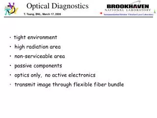
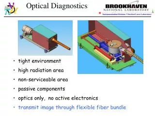
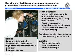
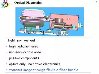
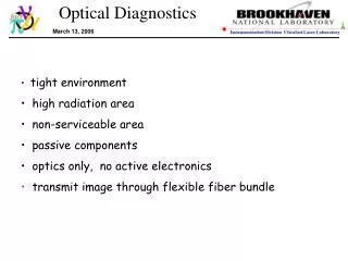
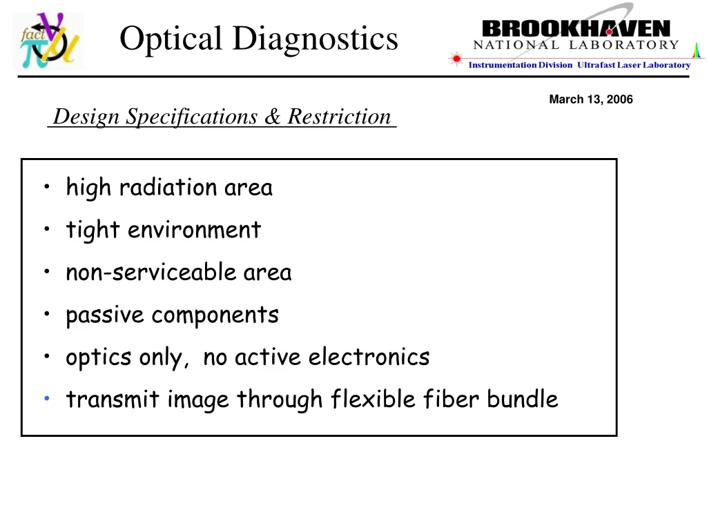
Optical Diagnostics March 13, 2006 Design Specifications & Restriction • high radiation area • tight environment • non-serviceable area • passive components • optics only, no active electronics • transmit image through flexible fiber bundle
Optical Layout Spherical mirror laser illumination image collection cm scale Ø6’’ Secondary Containment Works OK in this tight environment test target
Experimental Setup • Optical Components • 50/50 beam splitter: Edmund, 0.5 cm cube • spherical mirror: Edmund, f=3-in, D=3in< Au coated • small prism mirror: Edmund, 1x1x1.4 cm, Au coated • large prism mirror: Edmund, 2.5x2.5x3.54 cm. Au coated • imaging fiber Edmund: ⅛-in diameter, 12-µm core, 0.55 NA • illumination fiber: ThorLabs, 0.22 NA, SMA-905 840 -µm core • imaging lens: Sunex, f=0.38-cm, f/# 2.6, diagonal FOV 54°, φ1.4-cm x 2.0 cm test target
Cameras & Glass Imaging Fiber glass imaging fiber bundle Core size: 12 µm, diameter: 1/8” SMD 64KIM camera CCD size: 13.4 x 13.4 mm Pixels: 960x960 Single frame: 240x240 pixels 57,600 picture elements frame rate: 16 frames up to 1 µs/frame Reduced pixel size: 56 x 56 um FastVision CCD size: 15.4 x 12.3 mm Pixels: 1280x1024 Single frame: FPGA programable 1.3 M picture elements Frame rate: 500/s @ full resolution 500k/s @ 1x1280 CERN Olympus Encore PCI 8000S 4 kHz recording rate, 25 us electronic shutter Total fiber counts ~50,000 in 3.17 mm diameter Imaging ~243 x 243 fibers on 960 x 960 CCD array ~1 imaging fiber on ~4x4 pixels on full frame ~1 imaging fiber on ~1 pixel on a single frame
Laser Sources JDS Uniphase Laser diode, SDL-2300-L2 Power = 1 Watts Ith= 0.3 Amp λ -= 850 nm Laser diode, SLI 15-W, Class IV Power = 15 Watts Ith= 4.5 Amp λ -= 808 nm
Stationary images of NIR laser illumination
Chopper Image In Motion @ 4 kHz Stationary image 100 µs/frame Linear Velocity @ ~40 m/s 10 µs/frame 1 µs/frame 100 µs/frame with reflective mask
Optical Diagnostics System Design In Secondary Containment One set of optics per viewport Conceptual design completed
Irradiation Studies of Optical Components - I Before irradiation April, 2005 CERN, ~ April 15-24, 2005 Irradiation Condition : 1.4 GeV proton beam 4 x 10 15 proton Irradiation dose: equivalent to 40 pulses of 24 GeV proton beam 28 TP/pulse total of 1.2 x 10 15 proton Received radiation dose: 3231 Gy, ~ 323 krad Schott glass imaging fiber is not good
Irradiation Studies of Optical Components - II CERN, ~ Oct. 24, 2005 Irradiation Condition : 1.4 GeV proton beam 5 x 10 15 proton Irradiation dose: equivalent to 40 pulses of 24 GeV proton beam total of 5 x 10 15 proton Sumitomo fused silica imaging fiber is good
IGN-08/30 sample 0.3-meter 30,000 pixels Sumitomo Imaging Fibers Rad-hard to 1 Mrad continuous 10-20 meter available continuous 10 meter maybe available illumination uniformity
Fujikura Imaging Fibers Fujikura data, FIGH-30 A continuous 20-meter fiber 30,000 pixel imaging fiber illumination uniformity unofficial price info image after a continuous 20-meter long fiber official price info
30,000 picture elements Sumitomo IGN-08/30 Fujikura FIGH-30-850N Uniformity of Imaging Fibers NO significant difference in the uniformity of imaging fibers
Image Quality Comparison 30,000 pixels, 1-mm diameter 25 cm long 30 cm long FIGH-30-850N Sumitomo Fujikura IGN-08/30 $210/foot delivery in 3 months $78/foot delivery in 4 weeks NO significant difference in image quality Should go with Sumitomo fibers (20 meters have been ordered) camera SMD illumination NIR pulse, 10 us/frame
All-In-One Optical Setup The implementation of the new setup depends on the irradiation test lens imaging fiber – 1 mm illumination fiber fiber holder
Image Capture in All-In-One Optical Layout Setup 0.01 ms NIR pulse 0.1 ms NIR pulse Sumitomo IGN-08/30 Fujikura FIGH-30-850N
Controller Pipe System Water Jet System Main Pump Vacuum Pump Computer CCD Camera Water Jet Test, November 16 @ Princeton Univ. Front view Nozzle
Fast Camera Capture of Water Jet, November 16 @ Princeton Example : Tapered Nozzle with Straight (atm. condition) Velocity = Distance×FPS Observing Point Nozzle Exit Jet Moving Direction
Experimental Parameters Investigation For Water Jet Nondimensionalized Basic Equations ρ : density V : velocity D : diameter μ : viscocity Cp : specific heat P : pressure Г : surface tension k : thermal conductivity Boundary Condition (Free Surface) Later, Magnetic field effect should be considered for MHD experiment and the deformation of jet is going be investigated experimentally based on the parameters.
CCD camera Other Issues • Laser power increase to ~40 W/pulse (instead of 10 Watt/pulse) • Viewports: sapphire window • Number of viewports: 4 • Location of the viewports: 6-inches aparts • How many fast CCD camera ? 1 fast (1 µs) camera, ~3 slower (250 µs) camera ? • Potential to illuminate all viewports with one laser system • Make mockup with 1 viewports based on all-in-one optical layout fitting inside 6’’ • diameter secondary containment and optical feasibility test in terms of image quality