Download
1 / 20
200 likes | 349 Views
201 MHz and 805 MHz Cavity Developments in MUCOOL. Nufact 2002 Workshop, London, UK ( July 3, 2002). Derun Li Center for Beam Physics Lawrence Berkeley National Laboratory. Collaborators. J. Corlett, A. Ladran, R. MacGill, R. Rimmer (Jlab now), J. Wallig, M. Zisman

E N D
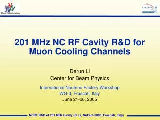
201 MHz and 805 MHz Cavity Developments in MUCOOL Nufact 2002 Workshop, London, UK ( July 3, 2002) Derun Li Center for Beam Physics Lawrence Berkeley National Laboratory
Collaborators J. Corlett, A. Ladran, R. MacGill, R. Rimmer (Jlab now), J. Wallig, M. Zisman Lawrence Berkeley National Laboratory Berkeley, CA 94720 D. Summers, M. Reep University of Mississippi, Oxford, MS A. Moretti, A. Rowe, Z.B. Qian,Y. Torun V. Wu Fermi National Accelerator Laboratory Batavia, IL J. Norem Argonne National Laboratory 201 and 805 MHz Cavity ... Derun Li
Introduction & Review • Development of 805 MHz Pillbox cavity • High shunt impedance and high acceleration gradient at order of 30 MV/m Z0 = 38 M/m • Allow for testing of Be windows with different thickness, coatings and as well as other windows • Study RF cavity operation issues under the influence of strong magnetic fields in solenoid and gradient modes • The cavity: design and status • The 805 MHz pillbox cavity design should allow for testing of different windows demountable windows to cover the beam irises (five Be windows, four Cu windows: two of them with Ti coatings on one side) 201 and 805 MHz Cavity ... Derun Li
Cavity Design & status Coupler Waveguide + window Thermo-couples or view ports Be (or Cu) windows Three more view ports on the equator Pillbox cavity 201 and 805 MHz Cavity ... Derun Li
Cavity Design Parameters • Frequency: 805 MHz • Shunt Impedance: • 38 M/m (Z0); 32 M/m (ZT2); {Z = V{0,T}2/P} • Quality factor: Q0 = 18,800 • Coupling Constant: • c = 1.0 at critical coupling; • <E> = 30 MV/m requires ~ 2 MW peak power and 350 watts average power, 52 watts on windows (Cu, 66 watts for Be) at duty factor of 1.8x10⁻⁴ (12 [FNAL=19] us pulse length and 15 Hz repetition rate). 201 and 805 MHz Cavity ... Derun Li
Manufacturing of the cavity The cavity was fabricated at University of Mississippi, brazed at Alpha Braze Comp. 201 and 805 MHz Cavity ... Derun Li
Cavity tuning (1) • The cavity was ready for final tuning for the frequency and coupling in June, 2001. (June 24-27, 2001 in University of Mississippi) • Before tuning: f = 803.198 MHz, c = 0.12 • After tuning: f = 805.486 MHz, Qext = 12,800 • After final brazing: Measurements done in November 14, 2001 at LBNL before shipping to Lab G at Fermilab: f = 804.946 MHz, c = 1.3, Q0 = 15, 000 201 and 805 MHz Cavity ... Derun Li
Cavity Tuning (2) Michael and Daniel assembling the cavity Cavity halves, coupler and Cu windows 201 and 805 MHz Cavity ... Derun Li
Cavity Tuning (3) • Frequency tuning (shortening the gap) • Coupler tuning (widening coupling slot and shortening the transition waveguide) Coupling slot 201 and 805 MHz Cavity ... Derun Li
Coupler Tuning • The couple slot angle • was widened from • 400 to 500 (two cuts) • in order to get close • to critical coupling. • Measurements of • the coupling agree • well with time domain • MAFIA simulations 201 and 805 MHz Cavity ... Derun Li
Milestones • The cavity was fabricated at Univ. of Mississippi • Final machine tuning was done in June 24-27, 2001 at University of Mississippi • Leak tight and last measurement in November 14, 2001 (air) at LBNL before shipping: f = 804.946 MHz, c = 1.3, Q0 = 15,000 • Low power measurement Lab G, Fermilab in March 12th 2002 (under vacuum): f = 805.135 MHz, c = 1.08, Q0 = 15,080 • Started RF conditioning in March 14th 2002 201 and 805 MHz Cavity ... Derun Li
Diagnostics (1) • Three view ports on the equator of the cavity • Three RF probes (adjusted to about -52 dB gain from the standard waveguide port) available for E & M field measurement • An optic bore-scope can be used to inspect the windows and inner surface of the cavity ( need lighting and TV/VCR for viewing and recording) • Maximum six thermo-couples can be attached to monitor temperature distribution on windows • Two compartments behind the cavity can be used to measure window deflection by frequency shift 201 and 805 MHz Cavity ... Derun Li
Diagnostics (2) • Equipment available at Lab G: x-ray, dark current + spectrum, forward + reflected RF power and arc detector • Lab G layout 201 and 805 MHz Cavity ... Derun Li
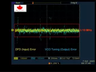
Test Results at Lab G • 33 MV/m with little sparking: 1 out of 25,000 pulses in April 22, 2002 • went through multipacting zones • reached about 29 MV/m in twenty days (2.2 MW peak power inside the cavity) • sparking at gradient of 30 MV/m and up (need to find the reasons, Cu windows to be inspected) • RF power was measured by forward power probe and RF probe inside the cavity agree within 10 % • Future test plan has been developed 201 and 805 MHz Cavity ... Derun Li
Test Plan (1) • A new thin Cu window is being made at LBNL • An alternative end plate by U. of Mississippi • better x-ray measurements • better dark current measurements • Through inspection of current Cu windows • Careful and complete log and documentation • Installation of the new Cu window and the end-plate • RF conditioning up to 20 - 24 MV/m 201 and 805 MHz Cavity ... Derun Li
Test Plan (2) • RF conditioning with magnet fields • Replace two Cu windows with Be windows with TiN coatings • RF conditioning with/without magnetic fields 201 and 805 MHz Cavity ... Derun Li
201 MHz cavity design 201 and 805 MHz Cavity ... Derun Li
201 MHz Cavity: windows Preliminary cavity design with water cooling channels and tuning mechanism. The cavity design accommodates either Be windows or a grid design. 201 and 805 MHz Cavity ... Derun Li
201 MHz Cavity Parameters * assumes 85% of the theoretical Q0 Thermal analysis by ANSYS code assuming 10 kW total rf heating power with water cooling for 21 cm radius and ~ 1.15 mm thickness Be window. 201 and 805 MHz Cavity ... Derun Li
Summary • 34 MV/m has been achieved for the 805 MHz • pillboxcavity • The high power tests will continue at Lab G of • Fermilab as planned • Surface damage and rf breakdown issues will be • studied carefully • Grid design is currently under investigation • 201 MHz cavity for MUCOOL is nearly completed • and ready for prototype 201 and 805 MHz Cavity ... Derun Li