Download
1 / 19
210 likes | 292 Views
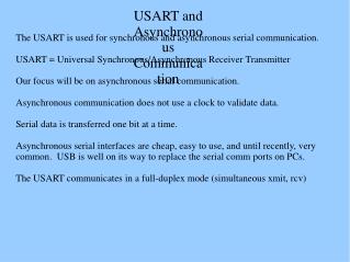
8251 USART. 8251. The 8251A is a programmable serial communication interface chip designed for synchronous and asynchronous serial data communication. It supports the serial transmission of data. It is packed in a 28 pin DIP. Pin details. Architecture. Arch - details.

E N D
8251 • The 8251A is a programmable serial communication interface chip designed for synchronous and asynchronous serial data communication. • It supports the serial transmission of data. • It is packed in a 28 pin DIP.
Arch - details • The functional block diagram of 825 1A consists five sections. They are: • Read/Write control logic • Transmitter • Receiver • Data bus buffer • Modem control.
Read/Write control logic • The Read/Write Control logic interfaces the 8251A with CPU, determines the functions of the 8251A according to the control word written into its control register. • It monitors the data flow. • This section has three registers and they are control register, status register and data buffer. • The active low signals RD, WR, CS and C/D(Low) are used for read/write operations with these three registers.
Read/Write control logic • When C/D(low) is high, the control register is selected for writing control word or reading status word. • When C/D(low) is low, the data buffer is selected for read/write operation. • When the reset is high, it forces 8251A into the idle mode. • The clock input is necessary for 8251A for communication with CPU and this clock does not control either the serial transmission or the reception rate.
Transmitter • The transmitter section accepts parallel data from CPU and converts them into serial data. • The transmitter section is double buffered, i.e., it has a buffer register to hold an 8-bit parallel data and another register called output register to convert the parallel data into serial bits. • When output register is empty, the data is transferred from buffer to output register. Now the processor can again load another data in buffer register.
Transmitter • If buffer register is empty, then TxRDY is goes to high. • If output register is empty then TxEMPTY goes to high. • The clock signal, TxC (low) controls the rate at which the bits are transmitted by the USART. • The clock frequency can be 1,16 or 64 times the baud rate.
Receiver • The receiver section accepts serial data and convert them into parallel data • The receiver section is double buffered, i.e., it has an input register to receive serial data and convert to parallel, and a buffer register to hold the parallel data. • When the RxD line goes low, the control logic assumes it as a START bit, waits for half a bit time and samples the line again. • If the line is still low, then the input register accepts the following bits, forms a character and loads it into the buffer register.
Receiver • The CPU reads the parallel data from the buffer register. • When the input register loads a parallel data to buffer register, the RxRDY line goes high. • The clock signal RxC (low) controls the rate at which bits are received by the USART. • During asynchronous mode, the signal SYNDET/BRKDET will indicate the break in the data transmission. • During synchronous mode, the signal SYNDET/BRKDET will indicate the reception of synchronous character.
Modem control • The MODEM control unit allows to interface a MODEM to 8251A and to establish data communication through MODEM over telephone lines. • This unit takes care of handshake signals for MODEM interface. • The 825 1A can be either memory mapped or I/O mapped in the system. • 8251A in I/O mapped in the system is shown in the figure. • Using a 3-to-8 decoder generates the chip select signals for I/O mapped devices. • The address lines A4, A5 and A6 are decoded to generate eight chip select signals (IOCS-0 to IOCS-7) and in this, the chip select signal IOCS-2 is used to select 8251A. • The address line A7 and the control signal IO / M(low) are used as enable for decoder. • The address line A0 of 8085 is connected to C/D(low) of 8251A to provide the internal addresses.
Modem control • The data lines D0 - D7 are connected to D0 - D7 of the processor to achieve parallel data transfer. • The RESET and clock signals are supplied by the processor. Here the processor clock is directly connected to 8251A. This clock controls the parallel data transfer between the processor and 8251A. • The output clock signal of 8085 is divided by suitable clock dividers like programmable timer 8254 and then used as clock for serial transmission and reception.
Modem control • The TTL logic levels of the serial data lines and the control signals necessary for serial transmission and reception are converted to RS232 logic levels using MAX232 and then terminated on a standard 9-pin D-.type connector. • In 8251A the transmission and reception baud rates can be different or same. • The device which requires serial communication with processor can be connected to this 9-pin D-type connector using 9-core cable • The signals TxEMPTY, TxRDY and RxRDY can be used as interrupt signals to initiate interrupt driven data transfer scheme between processor and 8251
Modem control • The CPU reads the parallel data from the buffer register. • When the input register loads a parallel data to buffer register, the RxRDY line goes high. • The clock signal RxC (low) controls the rate at which bits are received by the USART. • During asynchronous mode, the signal SYNDET/BRKDET will indicate the break in the data transmission. • During synchronous mode, the signal SYNDET/BRKDET will indicate the reception of synchronous character.
7 6 5 4 3 2 1 0 Mode register Number of Stop bits Baud Rate Parity enable 0: disable 1: enable 00: Syn. Mode 01: x1 clock 10: x16 clock 11: x64 clock 00: invalid 01: 1 bit 10: 1.5 bits 11: 2 bits Character length 00: 5 bits 01: 6 bits 10: 7 bits 11: 8 bits Parity 0: odd 1: even 8251 mode register
EH IR RTS ER SBRK RxE DTR TxE TxE: transmit enable DTR: data terminal ready RxE: receiver enable SBPRK: send break character ER: error reset RTS: request to send IR: internal reset EH: enter hunt mode 8251 command register
DSR SYNDET FE OE PE TxEMPTY RxRDY TxRDY TxRDY: transmit ready RxRDY: receiver ready TxEMPTY: transmitter empty PE: parity error OE: overrun error FE: framing error SYNDET: sync. character detected DSR: data set ready 8251 status register