Download
1 / 48
500 likes | 715 Views
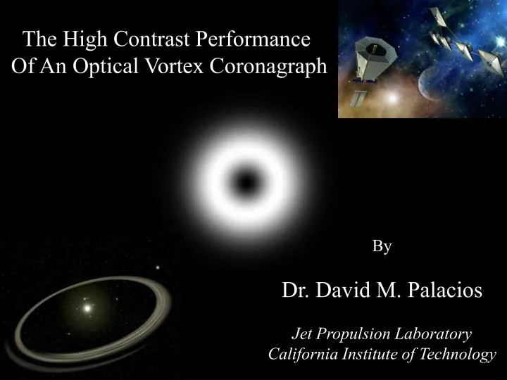
The High Contrast Performance Of An Optical Vortex Coronagraph. By Dr. David M. Palacios Jet Propulsion Laboratory California Institute of Technology. Acknowledgements. Stuart Shaklan Jet Propulsion Laboratory G.A. Swartzlander Jr. University of Arizona Dimitri Mawet University of.

E N D
The High Contrast Performance Of An Optical Vortex Coronagraph By Dr. David M. Palacios Jet Propulsion Laboratory California Institute of Technology
Acknowledgements Stuart Shaklan Jet Propulsion Laboratory G.A. Swartzlander Jr. University of Arizona Dimitri Mawet University of
Outline 1.) What is an Optical Vortex? 2.) Optical Vortex Mask Design 3.) Lyot Optimization 4.) Planet Light Throughput Efficiency 5.) Conclusions
What is an Optical Vortex? The Complex Field E(r,f,z;t)=A(r,z)exp(imf)exp[i(wt-kz)] Amplitude Phase
The Optical Vortex Mask Mask Thickness
Coronagraph Architecture Pupil OVM Lyot Stop FP L1 L2 L3 0 2m Incident Light Final Image Plane
The Optical Vortex Mask Mask Thickness
Ray Trace Analysis of the Vortex Mask n0 t dz d n1 d
The Vortex Core n0 dz d n1 d When c E Transmitted = 0
Output Amplitude Profile Transmitted amplitude for the E Polarization Transmitted amplitude for the Er Polarization
A Discrete Representation of an OVM Phase profile of an m=4 OVM dz dz d d 0 8
OVC Discretization Leakage Ideal OVC6 Pupil Discretized OVC6 Pupil Coronagraph Leakage!
Numerical Simulations 4096 x 4096 pixels 100 pixels in diameter 600 nm 27 0.2 microns 1.5 1 Array Size Pupil Size f # Mask Pixel Size n1
The Lyot Plane for Even Values of m m=2 m=4 m=6 Even charged OVMs theoretically cancel the entire pupil!
System Performance Contrast I(x,y) = Intensity with the occulter in place Iopen(x,y) = Intensity with the occulter removed o(x,y) = Occulter transmission function
Average Radial Contrast Average Contrast Between 2-3 /D m=6 Contrast r (/D)
Average Radial Contrast Average Contrast Between 2-8 /D m=6 Contrast r (/D)
Average Radial Contrast Average Contrast Between 4-5 /D m=6 Contrast r (/D)
Average Radial Contrast Average Contrast Between 4-10 /D m=6 Contrast r (/D)
Contrast vs. Lyot Size Average Contrast Between 2-3 /D Contrast m=2 m=4 m=6 Lyot Size (r/Rp)
Contrast vs. Lyot Size Average Contrast Between 2-8 /D Contrast m=2 m=4 m=6 Lyot Size (r/Rp)
Contrast vs. Lyot Size Average Contrast Between 4-5 /D Contrast m=2 m=4 m=6 Lyot Size (r/Rp)
Contrast vs. Lyot Size Average Contrast Between 4-10 /D Contrast m=2 m=4 m=6 Lyot Size (r/Rp)
Optimized Contrast Lyot Stop Radius = 0.8Pr Average Contrast 2-3 /D 2-8 /D 4-10 /D 4-5 /D m = 2 9.3x10⁻¹¹ 6.4x10⁻¹¹ 3.5x10⁻¹¹ 2.8x10⁻¹⁰ m = 4 5.1x10⁻¹¹ 4.1x10⁻¹¹ 2.5x10⁻¹¹ 1.2x10⁻¹⁰ m = 6 2.9x10⁻¹¹ 2.5x10⁻¹¹ 2.0x10⁻¹¹ 5.3x10⁻¹¹
Throughput Efficiency vs. Lyot Size Planet Located at 2/D Throughput m=0 m=2 m=4 m=6 Lyot Size (r/Rp)
Throughput Efficiency vs. Lyot Size Planet Located at 4/D Throughput m=0 m=2 m=4 m=6 Lyot Size (r/Rp)
Optimized Planet Light Throughput Lyot Stop Radius = 0.8Pr m=0 m=2 m=4 m=6 0.62 0.53 0.64 2/D 0.43 4/D 0.62 0.58 0.64 0.64
Is an Achromatic OVC Possible? C 5.999 6 6.001 m m must be maintained to ~5x10⁻⁴ across the bandpass!
Achromatic Holographic Vortex Coronagraph Lyot Stop Direction-compensating Grating f/30 beam Zero-order blocker Holographic Vortex
System advantages • Small inner working angle ~ 2/D • High throughput (theoretically 100%) • Same WFC architecture as other Lyot type coronagraphs • Small polarization effects (dependent on creation method) • Low aberration sensitivity to low-order Zernikes • Large search area (radially symmetric) • System can be chained in series
System Disadvantages • Broadband operation requires further research on new OV • creation techniques • Issues with mask Fabrication or hologram fabrication are just • beginning to be explored. • The Useful throughput decreases with stellar size making • operation at 2/D difficult on 0.1/D sized stars.
Conclusions • An m=6 vortex coronagraph meets TPF contrast requirements • Simulated 10-11 contrast at 2/D with a discretized OVM • OVM discretized with 0.2 micron pixels • Even charged OVMs theoretically cancel over the entire pupil • With discretization errors the Lyot stop radius = 0.8Pr • 53% throughput efficiency at 2/D • 62% throughput efficiency at 4/D near optimal of 64%
Aberration Sensitivity is the order of the aberration sensitivity 4th order linear sinc2 masks best demonstrated contrast 8th order masks presently being explored Vortex masks possess a 2mth order aberration sensitivity
The Aberration Sensitivity The Entrance Pupil Assuming (r,q) <<1, Mask Amplitude Transmission Function
More Math… The Exit Pupil Using the identity: The Approximate Exit Pupil
The Approximate Solution The first term in the expansion k=m All terms with less than an rm dependence vanish! The Intensity has a 2mth aberration sensitivity! For the m=5 case: 10th order sensitivity predicted!
Low Order Zernike Modes Z=4 Z=6 Z=7 Z=5 Z=8 Z=9 Z=10 Z=11
Numerical Simulations C Aberration size (waves peak to valley)
Coronagraph Comparisons 8th Order m=5 vortex Zernike # Improvement 2 8 9 3 8 9 4 4 -- 5 4 6 6 4 6 7 4 4 8 4 4 9 4 5 10 4 5 11 2 5 12 2 5
The Lyot and Focal Plane Profiles Pupil Vortex Mask Lyot Stop Lyot Plane Focal Plane /D
Amplitude Occulting Spots E(x,y) = A(x,y)exp[iF(x,y)] Hard Stop Sinc2(r)
The Lyot Stop Hard Stop Cat’s Eye Stop
The Final Image After Before
An Optical Limiting Technique Amplitude R/Rdiff
Contrast Simulations Contrast Image Compute the Radial Average Contrast