Download
1 / 77
770 likes | 786 Views
Embedded Systems Software: Modeling and Programming-- The Object-oriented Paradigm and The Unified Modeling Language (UML); Extensions to HW / SW Systems. Problems of software development. "problems" of software development: **conceptual integrity

E N D
Embedded Systems Software: Modeling and Programming-- The Object-oriented Paradigm and The Unified Modeling Language (UML); Extensions to HW / SW Systems
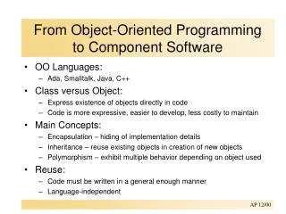
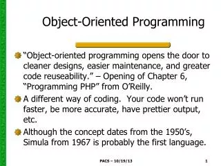
Problems of software development • "problems" of software development: • **conceptual integrity • **incremental build, progressive refinement • **large projects "differ" from small ones • programming paradigms (1950’s-present): attempts to deal effectively with these problems, make software easier to develop and to maintain
A Brief History: Computer Hardware, Computer Languages, Design Techniques 1950's:unstructured, no information hiding--”spaghetti” code, GOTO, flowcharts --machine code --assembly lang. --FORTRAN, LISP (Algol; COBOL) 1970s,1980s: structured, top-down design (“3 basic control structures, no GOTO”), modularity --Pascal, C, PL/I, Ada 1990’s: encapsulation, information-hiding, reuse, hardware/software codesign (from simulation languages developed much earlier, e.g., Modula, simula) --C++, Java 2000’s: info hiding; web languages; environments encapsulating multiple languages, styles --.NET, C#, Python, Perl, MATLAB, Mathematica, Labview, … Early machines—large, central (Eniac) Supercomputers, “Minicomputers”, PCs, multiuser machines, PICs Beowulf clusters, Spread of the Internet “Ubiquitous computing”, laptops,. Personal communication devices, multicore processors, GPUs wpclipart.com chilton-computing.org.uk http://en.wikipedia.org/wiki/PIC _microcontroller#History techxav.com cse.mtu.edu visual.merriam-webster.com http://www.amd.com/us-en/assets/content_type/Additional/ 43494A_QuadCore_Opt_Die_BLK_HRes.jpg textually.org http://t0.gstatic.com/images?q=tbn:ANd9GcS3J9yAV0YibC4keB8M_6hc0xh3sZYbbGKZUK-pHLzx7Lkek74w
OO class • Important basic OO concepts: • class: encapsulates data • structure (object) and associated methods (functions) • these may be declared public / private / protected • appropriate uses: • public: pass info to object or request info about object • (use "messages") (can be used by anyone) • private: modify object (can be used in class or by “friends”) • protected: for descendants (in class or by derived class and “friends”)
Record/class traditional: record (struct): functions to use or modify this record can be anywhere in the program OO: class concept supports encapsulation, information hiding OO Prog. DATA DATA DATA DATA DATA DATA DATA Procedural Prog.
Ex: Object data structures: A. Base class B. Derived class X Y Z W X Y Z A. B. Inheritance Useful OO techniques: Inheritance: ex: in a program modeling an ecosystem, we might have the relationships: wolf is carnivore; sheep is herbivore; grass is plant carnivore is animal; herbivore is animal animal is organism; plant is organism here the base class “organism” holds data fields which apply to all organisms, e.g., amount of water needed to survive two derived classes, plant and animal, hold information specific to each of these types of organisms, e.g., kind of soil preferred by plant the animal class also has two derived classes, wolf and sheep Inheritance allows the collection of common attributes and methods in "base" class and inclusion of more specific attributes and methods in derived classes
Polymorphism: base class can define a “virtual” function; appropriate versions of this function can be instantiated in each derived class (e.g., "draw" in the base class of graphical objects can have its own specific meaning for rectangles, lines, ellipses) Overloading: ex: cin >> num1; >> is overloaded "shift” ex: “+” can be overloaded to allow the addition of two vectors ex: a function name can be overloaded to apply to more than one situation; e.g., a constructor can be defined one way if initial values are given and a different way if initial values are not given Polymorphism and overloading
Templates Templates: example: template <class T> T method1 (T x) ….. can be specialized: int method1 (int x) float method1 (float y) usertype method1 (usertype a) templates promote reuse
Separate compilation • Separate compilation: • Typically, an object-oriented program can be broken into three sets of components: • definitions and prototypes (text files, “header files”) • implementations (compiled--source code need not be available to user) • application program--uses the classes defined in header files and supported by the implementation files • This strategy promotes reuse and information hiding
Use / Misuse of object-oriented paradigm • Note that no paradigm is misuse-proof • DISCUSSION: Is the OO paradigm useful for mixed hardware / software systems?
Using OO & (a subset of) UML in a project: design; design for testability Design: “top-down”; Test: “bottom-up” : “Design for testability” determine specifications: use cases system tests determine classes [modules] and connections (static behavior): ER or class diagrams; CRC cards module (“black box”) tests model dynamic behavior: interaction (object message) diagrams activity diagrams state diagrams (fsm’s) sequence diagrams [ individual class methods “white box” or “glass box” tests] dynamic module interactions / “boundary” behavior
UML: stands for "unified modeling language” unifies methods of Booch, Rumbaugh (OMT or Object Modeling Technique), and Jacobson (OOSE or Object-Oriented Software Engineering) mainly a modeling language, not a complete development method Early versions -- second half of the 90's Not all methods we will use are officially part of the UML description UML: a language for specifying and designing an OO project
USE CASES: a part of the ”Unified Modeling Language" (UML) which we will use for requirements analysis and specification each identifies a way the system will be used and the "actors" (people or devices) that will use it (an interaction between the user and the system) each use case should capture some user-visible function and achieve some discrete goal for the user an actual user can have many actor roles in these use cases an instance of a use case is usually called a "scenario” Use case will typically have graphical & verbal forms Use cases
Example: cellular network place and receive calls use case (based on Booch, Rumbaugh, and Jacobson, The Unified Modeling Language User Guide) Example use case Text description --Use case name (cellular network place and receive calls) --Participating actors (cellular network and human user) --Flow of events (network or user accesses network to use its functionality) --Entry condition(s) (user accesses network using device or password) --Exit condition(s) (call completed lost or network busy) --Quality requirements (speed, service quality) System boundary Use case diagram—summarizes, provides system overview Text description—gives important details
use case Text description: Use case name Participating actors Flow of events Entry condition(s) Exit condition(s) Quality requirements
Encounters an error condition Arms/disarms system Responds to alarm event Use case—detailed example (Pressman) Example: “SAFEHOME” system (Pressman) Use case: InitiateMonitoring Participating actors:_______ Flow of events:_______ Entry condition(s):_______ Exit condition(s):_______ Quality requirements:_______ (What is in HW, what is SW?) Homeowner Accesses system via internet Sensors System administrator Reconfigures sensors and related system features Pressman, p. 163, Figure 7.3
Use case additions—simplifications of use case descriptions • A. Include: one use case includes another in its flow of events (cases A and B both include case C) • Extend: extend one use case to include additional behavior (cases D and E are extensions of case F) <<include>> A C B <<include>> <<extend>> D F E <<extend>>
Use case additions • C. Inheritance: one use case specializes the more general behavior of another G and H specialize behavior of J) G J Authenticate with password authenticate H Authenticate with card
Use case continued Examples: what would be a hardware use case for the following? What might be a software use case? vending machine traffic light Use case name Participating actors Flow of events Entry condition Exit condition Quality requirements
System Tests • Note: • Use cases can form a basis for system acceptance tests • For each use case: • Develop one or more system tests to confirm that the use case requirements will be satisfied • Add explicit test values as soon as possible during design phase • These tests are now specifically tied to the use case and will be used as the top level acceptance tests • Do not forget use cases / tests for performance and usability requirements (these may be qualitative as well as quantitative)
Use case writing guide: --each use case should be traceable to requirements --name should be a verb phrase to indicate user goal --actor names should be noun phrases --system boundary needs to be clearly defined --use active voice in describing flow of events, to make clear who does what --make sure the flow of events describes a complete user transaction ---if there is a dependence among steps, this needs to be made clear --describe exceptions separately --DO NOT describe the user interface to the system, only functions --DO NOT make the use case too long—use extends, includes instead --as you develop use cases, develop associated tests 21
Analysis model (UML version): --functional model (use cases and scenarios) --analysis object model (static: class and object diagrams) --dynamic model (state and sequence diagrams) As system is analyzed, specifications are refined and made more explicit; if necessary, requirements are also updated
Example: an activity diagram for analyzing a system you are building:
Class (modules) and object diagrams: Identify Objects from Use Case Specifications: USE ENDUSER’s TERMS AS MUCH AS POSSIBLE Entity objects: “things”, for example: --nouns (customer, hospital, infection) --real-world entities (resource, dispatcher) --real-world activities to be tracked (evacuation_plan) --data sources or sinks (printer) Boundary objects: system interfaces, for example: --controls (report(emergencybutton) --forms (savings_deposit_form) --messages (notify_of_error) Control objects: usually one per use case --coordinate boundary and entity objects in the use case Use the identified objects in a sequence diagram to carry out the use case
Other common types of classes which the developer can look for include: • tangible things, e.g., Mailbox, Document • system interfaces and devices, e.g., DisplayWindow, Input Reader • agents, e.g., Paginator, which computes document page breaks, or InputReader • events and transactions, e.g., MouseEvent,CustomerArrival • users and roles, e.g., Administrator, User • systems, e.g., mailsystem (overall), InitializationSystem (initializes) • containers, e.g., Mailbox, Invoice, Event • foundation classes, e.g., String, Date, Vector, etc. Common classes
Sequence Diagram Sequence Diagram: a sequence diagram also models dynamic behavior typically a sequence diagram shows how objects act together to implement a single use case messages passed between the objects are also shown sequence diagrams help to show the overall flow of control in the part of the program being modeled they can also be used to show: concurrent processes asynchronous behavior
Sequence Diagram--Syntax Objects in the sequence diagram are shown as boxes at the top below each object is a dashed vertical line--the object’s “lifeline” an arrow between two lifelines represents each message arrows are labeled with message names and can also include information on arguments and control information two types of control: condition, e.g., [is greaterthan zero] iteration, e.g., *[for all array items] “return” arrows can also be included
Useful object relationships • These diagrams represent the relationships between the classes in the system. These represent a static view of the system. • There are three basic types of relationship: • inheritance ("is-a") • aggregation ("has-a”) • association ("uses") • These are commonly diagrammed as follows: ER diagrams
manager employee is-a: draw an arrow from the derived to the base class: ER diagram: is-a
car tire 1 4 has-a: draw a line with a diamond on the end at the "container" class. Cardinalities may also be shown (1:1, 1:n, 1:0…m; 1:*, i.e., any number > 0, 1:1…*, i.e., any number > 1): ER diagram--has-a tire & car can exist independently—shared aggregation person arm is part of the person– composition aggregation arm 1 2
uses or association: there are many ways to represent this relationship, e.g., ER diagram--uses employs 1 company car gasstation * * * n employee 1 works for
CRC cards: class--responsibilities--collaborators cards "responsibilities" = operators, methods "collaborators" = related classes (for a particular operator or method) Make one actual card for each discovered class, with responsibilities and collaborators on the front, data fields on the back. CRC cards are not really part of UML, but are often used in conjunction with it. CRC cards
Class Mailbox Operations Relationships (Responsibilities) (Collaborators) get current message Message, Messagequeue play greeting ----------- Example (based on Horstmann, Practical Object-Oriented Development in C++ and Java): front back CRC card--example Class Mailbox Queue of new messages Queue of kept messages Greeting Extension number Passcode
State Diagram State Diagram (~ FSM): another way of adding detail to the design--models dynamic behavior describes all the possible states a particular object can be in and how that object's state changes as a result of events that affect that object usually drawn for a single class to show behavior of a single object used to clarify dynamic behavior within the system, as needed
State Diagram--Properties A state diagram contains a "start" point, states, and transitions from one state to another. Each state is labeled by its name and by the activities which occur when in that state. Transitions can have three optional labels: Event [Guard] / Action. A transition is triggered by an Event. If there is no Event, then the transition is triggered as soon as the state activities are completed. A Guard can be true or false. If the Guard is false, the transition is not taken. An Action is completed during the transition.
State Diagram--Example Example: this state diagram example for an "order" in an order-processing system is from Fowler and Scott, UML Distilled (Addison-Wesley, 1997): start /get first item [not all items checked] /get next item [all items checked && all items available] Dispatching Checking initiate delivery check item [all items checked && some items not in stock] delivered item received [all items in stock] Delivered Waiting item received [some items not in stock]
Example—bank simulation (Horstmann) Horstmann, Mastering Object-Oriented Design in C++, Wiley, 1995 Teller 1 Teller 2 Customer 3 Customer 2 Customer 1 Teller 3 Teller 4
Bank Statistics Customer Bank Application Arrival Departure EventQueue Event Example—bank simulation (Horstmann), cont. An initial solution (Horstmann, p. 388):
Bank Statistics Customer Bank Simulation Arrival Departure EventQueue Event Example—bank simulation (Horstmann), cont. An improved solution (Horstmann, p. 391):
Bank Statistics Bank Statistics Customer Bank Customer Bank Application Simulation Arrival Arrival Departure Departure EventQueue EventQueue Event Event Comparison What simplifications have been made? Why?
Example: How would we use the tools described so far to design a “smart” vending machine? How would we develop test cases at each stage? Use cases? Class diagram? Sequence diagram? Classes / CRC cards?
Software modeling for embedded systems: static and dynamic behavior
Important concepts in embedded systems: --concurrency: the system can handle multiple active independent or cooperating objects at the same time --thread [of control]—models sequential execution of a set of instructions; embedded system may have several concurrent threads operating simultaneously --persistence—how long does a software object last? Examples: Temporary variable Global variable Software module
Note that “UML” syntax can vary among implementations; Previously we looked at one implementation, here we consider examples from the text table_05_00 table_05_00
UML Use case diagram—example-note that this author omits “system boundary”- fig_05_01 fig_05_01
UML: Use case diagram (text); note exceptions fig_05_02 fig_05_02
UML: Class diagram (“CRC card”) Class name data Methods (responsibilities and collaborators) fig_05_03 (+ collaborators) fig_05_03
UML: class relationships: inheritance fig_05_04 fig_05_04