Download
1 / 18
180 likes | 286 Views
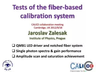
Ivo Pol á k polaki@fzu.cz Notched fibre light distribution systems A Set-up, with provisional fibre layout QRLED driver generate single p.e. Spectra at HBU0 Saturation curve needs better light coupling Conclusions. LED notched fibre system short HBU0 party with QMB6.

E N D
Ivo Polák polaki@fzu.cz Notched fibre light distribution systems A Set-up, with provisional fibre layout QRLED driver generate single p.e. Spectra at HBU0 Saturation curve needs better light coupling Conclusions LED notched fibre systemshort HBU0 party with QMB6 Ivo Polák, FZU, Prague
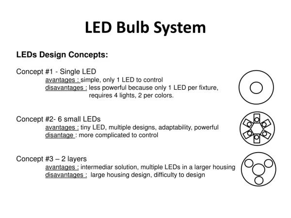
Ivo Polák, FZU, Prague Light distributed directly by microLED to the scintillator - distributed LEDs Flashing UVLED - 2 methods • Light distributed by notched fibres smd UVLED Institute of Physics ASCR, Prague, (= FZU) Kobe University DESY Hamburg UNI Wuppertal
Ivo Polák, FZU, Prague Notched fiber system Notched fibre routed at HBU0, taps illuminates the scintillators via special holes • advantage – tuneable amplitude of LED light from 0 to 50 mips • Variation of LED amplitude does not affect the SiPM response readout • LED circuit and LEDs enable optical pulses with around 5ns width • Spread of light intensity from notches can be kept under 20% • disadvantage LED with control unit outside the detector volume • Notched fibre production is not trivial Nice idea, but... Spiroc1 area is not working Spiroc2 Spiroc1
Ivo Polák, FZU, Prague Notched fibre layoutnice blue taps shins to alignement pins Spiroc 2 area Fibre were fixed by strips of tape in position...
Setup QMB6 + HBU0 • From HBU0 (calib board): • signal T-calib LVDS only • 60ns Delay • power +15V/0.16A • CANbus slow-control • One UVLED 5mm • One Notched fibre Almost plug and play Control: LabView 8.2 exe-file, One PC with DAQ, USB --> CAN Ivo Polák, FZU, Prague
Control panel of QMB6 in LabView 8.2 • Controls individual LED amplitude • LED Enables • Trigger mode ext/internal • Measure temperature • CANbus control • It can work as Exe file Ivo Polák, FZU, Prague
Ivo Polák, FZU, Prague Next day we found a misalignment of the fibre Electrical tape and bended fibre is not the right combination!
Ivo Polák, FZU, Prague QMB6 ON/OFF test ON means T-calib on, LED off OFF means +15V power off NO pedestal shift! NO unwanted ground coupling!
Ivo Polák, FZU, Prague Single p.e. spectrum Calibration mode, High Gain
Single photoelectron spectra with CMB and QRLED LED light 400nm to SiPM on 5mmsci tile QRLed drive SiPM, single p.e. spectra taken at Prague SEP’09 NEW • CMB in tuning position at AHCAL TB 2007 CERN OLD one of the single p.e. spectra More info about CMB can be found at: http://www-hep2.fzu.cz/calice/files/ECFA_Valencia.Ivo_CMB_Devel_nov06.pdf Ivo Polák, FZU, Prague
Ivo Polák, FZU, Prague Linearity test (it means a saturation curve) • Settings: • Cf = 400fF • Low gain mode • We do not see saturation effect, yet. • Better optical coupling alignement is a must. • Higher LED pulse can be made with larger pulse-width (3.7 → 7ns) Very preliminary
Ivo Polák, FZU, Prague Conclusionsto common test HBU0 with QMB6 • Easy implementation, almost plug and play instalation • QRLED driver has tunable light amplitude • Both methods of light distribution are tested in HBU0 EUDET prototype • With QMB6 we can see a nice single p.e. spectra, similar to distributed LEDs • We do not see saturation of SiPM yet, better optical coupling is a must. We have to focuse on this detail. • We would like to make more tests in the future, focusing on the optical coupling • Special thanks to Mathias Reinecke and FLC group.
Ivo Polák, FZU, Prague Back up
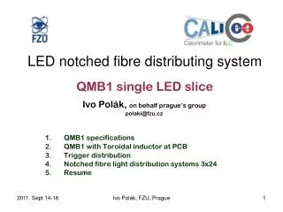
Quasi-Resonant LED driver • Less RFI • PCB integrated toroidal inductor (~35nH) • Fixed pulse-width (~4ns) PIN signal 4ns/div LED current 1V => 1A 1App Ivo Polák, FZU, Prague
6-LED QR driver Main Board = QMB6 Ivo Polák, FZU, Prague • Consists: • 6 QR LED drivers • 2 PIN PD preamps • CPU + communication module, CANbus • Voltage regulators • temperature and voltage monitoring 17
Ivo Polák, FZU, Prague Details of distributed LEDs Small UV LED, smd size 1206 and 0603 top bottom