Download
1 / 21
210 likes | 383 Views
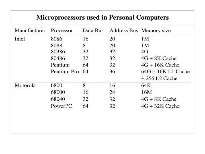
Microprocessors used in Personal Computers. The Memory Map of a Personal Computers. Transient Program Area (TPA): Holds the operating system (interrupt vectors, DOS BIOS, devices drivers, Command.com) and application programs.

E N D
The Memory Map of a Personal Computers • Transient Program Area (TPA): Holds the operating system (interrupt vectors, DOS BIOS, devices drivers, Command.com) and application programs. • System Area: Holds the ROM BIOS, the video buffer area, and the BASIC language ROM. • Extended Memory: Memory above the 1M conventional memory found in AT compatible computers . Its size depends on the RAM installed on the motherboard, and is limited by the size of the processor’s address bus.
The Flag Register • Z (zero): This flag is set to one if the result of the last arithmetic or logic instruction is zero. • S (sign): This flag is set to one if the MSBit of the result of the last arithmetic or logic instruction is one, indicating a negative number . • C (carry): This flag is set to one if the last arithmetic instruction gave a carry out or a borrow in. • O (overflow): This flag is set to one if the result of the last arithmetic operation on signed numbers exceeded the capacity of the destination register.
80x86 Modes of operation • Protected mode • Programs are given separate memory areas (segments) • Programs are not allowed to access memory outside of their segments • Real-address mode • Environment of 8086 processor • Direct access to system memory and hardware devices • The operating system could crash • System management mode • Provides an operating system for implementing power management and system security functions (computer manufacturers)
Segmentation • Segmentation is used to allow relocation of programs, i.e. programs can be loaded on different memory areas and still run correctly. • Segmentation is used in the 8088/8086 microprocessors to allow the generation of 20-bit addresses using 16-bit registers. • In the Real Mode Operation a 20-bit address (effective address) is obtained by shifting the segment address 4 bits to the left (X10H) and then adding the offset address. • The offset address is specified in the program. The segment address is specified by the operating system whenever the program is loaded. • The code segment holds the machine codes of the program.The Instruction Pointer specifies the offset address in the code segment. • The data segment holds the data used by the program. Most data references are specified in the data segment. • The stack segment holds the stack of the program. The offset address in the stack segment is specified with the registers SP and BP. • The extra segment is used as a data segment by some data movement instructions.
Segmentation (Example) If DS =1600H find the maximum area occupied by the data segment. Find also the effective address, if the offset address is 1F00H. Starting address = DS X 10H = 1600H X 10H = 16000H Ending address = Starting address + FFFF = 16000H + FFFFH = 25FFFH Effective address = Segment:Offset = 1600:1F00 = Segment address X 10H + Offset = 1600H X 10H + 1F00H = 16000H + 1F00H = 17F00H
Assembler Directives • Directives are instructions given by the programmer to the assembler on how to assemble the program. • Directives are not part of the instruction set of the microprocessor. • The use of directives might vary from assembler to assembler. • Some of the MASM 6.12 assembler directives are: • ORG (Origin): Tells the assembler where to store the machine code of the next instruction. • EQU (Equate): Tells the assembler to assign a value to an identifier. • SEGMENT: Tells the assembler to begin a new segment. • ASSUME: Tell the assembler to associate a segment with a segment register. • PROC (Procedure): Tells the assembler to begin a new procedure. • MACRO: Assigns the sequence of instructions to an identifier. • END: Ends a program, segment (ENDS), a procedure (ENDP), or a macro (ENDM).
Data Definition Directives • Data Definition directives tell the assembler to store the specified data in the next memory locations. Data that occupies more than one location is stored with the LSByte in the lower address. • (DB) Define Byte (1 byte or 8 bits - Same as BYTE) • (DW) Define Word (2 bytes or 16 bits - Same as WORD) • (DD) Define Double Word (4 bytes or 32 bits - Same as DWORD) • (DQ) Define Quad Word (8 bytes or 64 bits - Same as QWORD) • (DT) Define Ten Bytes (10 bytes or 80 bits - Same as TBYTE) Examples: • ABC DB 26H ;ABC=26H • XYZ DB 35H,87H,0A4H ;XYZ= {35H,87H,A4H} • YOU DB ‘JOHN’ ;YOU = ‘JOHN’ • VAL DW 1254H ;VAL = 1254H • X1 DB ? ;X1 = UNSPECIFIED • X4 DB 3 DUP(20H) ;X4 = {20H,20H,20H} • N1 DB 123H ;INVALID
Data Definitions (Example) Show the content of the memory based on the following data definitions: ORG 100H VAL1 EQU 21H AB10 DB 37 NEW DB 23H,56H,’$’ LOT DW 1245H XY11 DB ‘NEXT’ A123 DD 123H B561 DB 4 DUP(40H) VAL2 DB VAL1
Format of DOS programs • All programs must have a code and a stack. • Code is the part of the program that contains the instructions of the program. • Stack is an area in the RAM used by the system to store return addresses, and by the programmer to store temporarily data. It is a Last In First Out (LIFO) buffer. • Programs can also have a data area, where all data (variables) is stored. • There are two basic types of programs: • Commands (.COM). The data and the stack of the program are part of the Code segment. The stack is always located at the end of the segment. The first 256 bytes of the segment are reserved. • Executable (.EXE). The code and stack and data of the program are located in different segments.
Format of the .COM programs CSEG SEGMENT PARA 'CODE’ ;Start a Code segment ASSUME CS:CSEG, DS:CSEG, SS:CSEG ORG 100H ;Reserve first 256 locations START: JMP MAIN ;Skip data area {Place the data of the program here} MAIN PROC NEAR ;Beginning of main procedure {Place the code of the program here} RET ;Get return DOS address MAIN ENDP ;End of main procedure CSEG ENDS ;End of the segment END START ;End of the program
Addressing Modes Addressing mode refers to the way the data needed by an instruction is specified.
Immediate Addressing Mode • The data needed is specified as a number in the machine code of a program. The data is specified by the programmer: • as a numeric operand in the instruction, e.g. MOV AL,87H ;AL 87H MOV CX,34A6H ;CX 34A6H MOV BL,8C2H ;Invalid (Data Mismatch) • or as a label. The actual value is determined by the assembler. e.g. MOV BX,OFFSET VAL3 ;BX Address of VAL3 MOV AH,CON1 ;AH CON1
Register Addressing Mode • Both of the operands are the contents of registers. e.g. MOV AL,BH ;AL BH MOV BX,CX ;BX CX MOV AX,DL ;Invalid (Data Mismatch) • Example:
Direct Addressing Mode • One of the operands is the contents of the memory location that is specified directly in the instruction. e.g. MOV AL,[1008H] ;AL [1008H] MOV BX,VALUE ;BX [VALUE]
Register Indirect Addressing Mode • One of the operands is the contents of the memory location that is specified by a register, or a combination of registers and an offset, in the instruction. • Index: Use of SI or DI to specify a memory location. e.g. MOV AL,[SI] ;AL [SI] • Base: Use of BX or BP to specify a memory location. e.g. MOV AH,[BP] ;AL [BP] • Base Relative: Use of BX or BP in combination with an offset to specify a memory location. e.g. MOV AL,[BX+ 2] ;AL [BX + 2] • Base Relative plus Index: Use of BX or BP in combination with an index register (SI or DI) and an offset to specify a memory location. e.g. MOV AL,[BX+SI+8] ;AL [BX+SI+8] MOV BX,ARR[BX+DI] ;BX ARR[BX+DI]
Examples • MOV ECX,6F23458H • MOV SI, -1 • MOV DS,1000H • MOV AL,100H • MOV 123,DH • MOV 0FABH,AX • MOV SI, CL • MOV EDX,ESI • MOV EDX,-2 Indicate whether or not each of the following MOV instructions is valid or invalid • MOV AX,BX • MOV DX,BL • MOV ECX,EDX • MOV SI,DI • MOV DS,AX • MOV AL,DH • MOV AX,DH • MOV IP,AX • MOV SI,CL • MOV EDX,AX • MOV AX,ES • MOV AX,16 • MOV DX,7F65H