Download
1 / 13
130 likes | 232 Views
IDPU Power Control Board (PCB) Craig Domeny University of California - Berkeley. Power Control Board Overview / Documentation Block Diagram Power Sources Service / Load Classes Circuit Design Actel Power / Thermal Analysis Test. Overview / Documentation. Electrical Specification

E N D
IDPU Power Control Board (PCB) • Craig Domeny • University of California - Berkeley
Power Control Board • Overview / Documentation • Block Diagram • Power Sources • Service / Load Classes • Circuit Design • Actel • Power / Thermal Analysis • Test
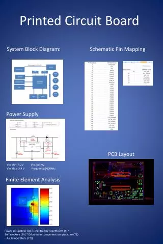
Overview / Documentation • Electrical Specification • Captured in THM_PCB_001 revision F • Details Power Switching, Housekeeping, and Commanding Requirements • Provides connector specifications and pin-outs • Electro-Mechanical • Connectors • One VME standard connector 3x32 (96pin) M55302 (Class1) • Two 15-pin Sub-D high density connectors on front panel • Two 26-pin Sub-D high density connectors on front panel • One 44-pin Sub-D high density connector on front panel • Board • Board-to-board Spacing is 0.585” • PCB shares board with FGE
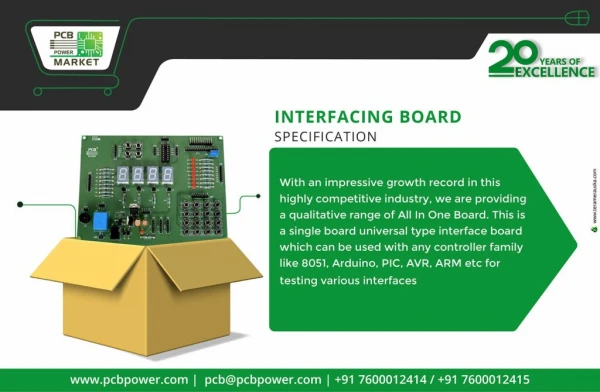
FGE PCB
Power Sources Power Sources (2): Spacecraft Power Bus (28V nominal) SPB Motors Axial, SCM, FGM Boom Frangibolts SPB Doors (Nitinol wire) LVPS (Backplane) IDPU Circuits ESA Covers (Nanomuscle) SST Attenuators (Nanomuscle)
Service / Load Classes Service / Load Classes: SPB Motors Nominal; 100mA@28V (Inrush 1Amp) Axial, SCM, FGM Frangibolts Single; 1.1Amp (40 seconds) Redundant; 2.2Amps (40 seconds) Instruments Command-enabled (Actel) Current limited +2.5VD, +5VD, +5VA, -5VA, -8VA, +10VA, -10VA, +28VA (+8VA derived from +10VA) ON/OFF control to the output service rails (Actel)
Service / Load Classes Service / Load Classes: ESA Covers, SST Attenuators Nanomuscle; 600mA, 100miliseconds SPB Doors 2Amps, 1 second
Circuit Design • IDPU Current Limiter / Monitor
Circuit Design • +10VA to +8VA Regulator
Actel FPGA Actel FPGA • Processes commands from the backplane • Enables/forces IDPU input service sources • Switches IDPU service outputs • Processes analog housekeeping muxes • Forwards SPB turns-counter switches to mux
Power / Thermal Analysis • Worst-case Offenders (Ambient specified at 55degC) • SCM Frangibolts (2.2 Amps^2) * 0.35Ohms = 1.7W • SPB Doors (2.0 Amps^2) * 0.35Ohms = 1.4W • Both use IRF9130… • 25W @ Tc = 25 degC • Junction rated -55 to 150 degC • θjc = 5 degC/watt • PDmax = 150deg - 55deg / 5deg per watt • IRF9130… Pdmax = 19 watts
Test • Test Load Board • Plugs into backplane; uses free-wires to front panel connectors • Relies on PCB Actel-based CDI command functionality • Simulates all service-rail output loads • Operator-switched overcurrent tests current limiter • CDI-command forces overcurrent, defeats limiter • Simulates inrush currents and closed-loop actuator functions • Simulates SPB turns-counting switches