Download
1 / 26
260 likes | 281 Views
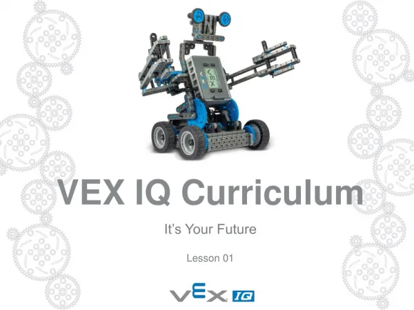
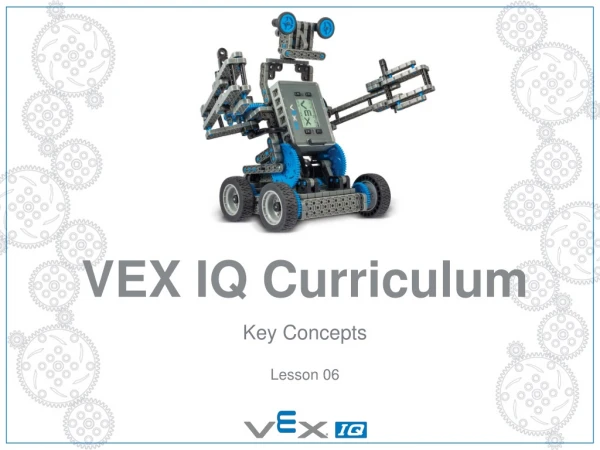
VEX IQ Curriculum. Mechanisms Lesson 07. Project Overview. Its Your Future Let’s Get Started Your First Robot Simple Machines & Motion Chain Reaction Challenge Key Concepts Mechanisms Highrise Challenge Smart Machines Chain Reaction Programming Challenge Smarter Machines

E N D
VEX IQ Curriculum Mechanisms Lesson 07
Project Overview • Its Your Future • Let’s Get Started • Your First Robot • Simple Machines & Motion • Chain Reaction Challenge • Key Concepts • Mechanisms • Highrise Challenge • Smart Machines • Chain Reaction Programming Challenge • Smarter Machines • Highrise Programming Challenge
MECHANISMS The purpose of this lesson is for students to learn about robotic mechanisms, their design, and the corresponding math and science concepts.
LESSON 07 STARTER Prints out for the lesson Build Instructions Student hand-out Teacher US guide sheet Mechanisms student hand-out 1, 2, 3, 4, 5, 6, 7, 8, 9
LESSON 07NB: you might wish to deliver this lesson in twice the time of a single lesson
LESSON 07 STARTER Learning objective: Learn about DC Motors. Learn about and apply knowledge of Gear Ratio. Learn about Drivetrains. Learn about Object Manipulation. Learn about lifting mechanisms. Task 1 : Matching exercise Looking through the student hand-out, Fill in the missing gaps on your worksheet by picking words from the word bank at the top of the page.Your teacher will take you through the worksheet in order top to bottom, so when you hear some information that is missing, put it in!
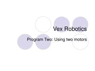
LESSON 07 Actuatorsare used to act upon an environment, usually for moving or controlling a mechanism or system. Actuators drive everything that moves on a mobile robot. The most common type of actuator is a motor; in particular, VEX IQ utilizes Direct Current (DC) Motors. DC Motors convert electrical energy into mechanical energy through the use of electromagnetic fields and rotating wire coils. When a voltage is applied to a motor, it outputs a fixed amount of mechanical power (usually to a shaft, gear, and/or wheel), spinning at some speed with some amount of torque.
LESSON 07 Motor Loading Motors apply torque in response to loading. Motor Loading happens when there is any opposing force (such as friction or a heavy mass) acting as a load and requiring the motor to output torque to overcome it. The higher the load placed on a motor output, the more the motor will “fight back” with an opposing torque. However, as you learned in the Key Concepts Unit, since the motor outputs a fixed amount of power, the more torque the motor outputs, the slower its rotational speed. Motor applies torque to overcome the friction of a wheel turning against the ground Current Draw A DC Motor draws a certain amount of electrical current (measured in amps) depending on how much load is placed on it. As the load increases on the motor, the more torque the motor outputs to overcome it and the more current the motor draws. If you keep increasing the load on a motor, it eventually stops spinning or stalls.
LESSON 07 Task 2: Build and experiment with the VEX IQ Gear Ratio Simulator. Gear Ratio Basics As you learned in other lessons, making a Gear Ratio change is one of the easiest ways to change Mechanical Advantage in a mechanism or system to achieve desired speed and/or torque. Gear Ratio expresses the relationship between a Driving Gear (the gear connected to the input power source, such as a motor) and a Driven Gear (the gear connected to the output, such as a wheel or mechanism) in a system. When you have a system with a Driving Gear that is SMALLERthan the Driven Gear you will increase Torque and decrease Speed:
LESSON 07 When you have a system with a Driving Gear that is LARGERthan the Driven Gear you will increase Speed and decrease Torque. Making this kind of change to Mechanical Advantage is helpful when you are trying to lift or move faster mechanically, you don’t require the ability to lift heavy objects, and/or you favour agility over pushing ability in a drivetrain.
LESSON 07 Expressing Gear Ratio and Gear Reduction Both Gear Ratio and Gear Reduction are mathematical expressions that describe the relationship between a Driving Gear and a Driven Gear. However, It’s important to understand the different, but similar ways they are expressed. Both use the number of teeth on each gear as key values, although their order is reversed. Gear Ratio is expressed this way: (Driving Gear Teeth) : (Driven Gear Teeth) Gear Reduction is expressed in reverse: (Driven Gear Teeth) / (Driving Gear Teeth) Note: Gear Reduction is seen as a fraction that is often reduced to simplify the expression
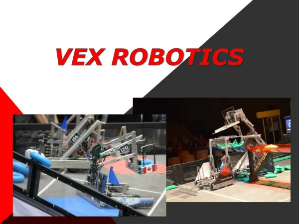
LESSON 07 So, given the example right of a 12-tooth Driving Gear and a 36-tooth Driven Gear: Gear Ratio = 12 : 36 “12 to 36 Gear Ratio” Gear Reduction = 36 / 12 or 3 / 1 “36 to 12 Gear Reduction” or “3 to 1 Gear Reduction” Mobile and Competition robots will vary greatly depending on the tasks they are designed for. However, one thing common among them is that they usually have some method for moving. The robotic subsystem that provides the ability to move is often known as a Drivetrain. Drivetrains may come in many different forms – two examples are wheels or treads (like a tank). The wheeled, rolling drivetrain is the most common one found in competition robotics and one of the most popular in the entire industry…
LESSON 07 Gear Trains and Idler GearsA simple Gear Train is a connected set of rotating gears that transmits power from an input (like a Driving Gear connected to a motor) to an output (like a Driven Gear connected to a wheel or mechanism). Simple Gear Trains can have any number of gears in a single row. All gears in between the Driving Gear and the Driven Gear that only transmit power are known as Idler Gears. Idler Gears have NO EFFECT on Gear Ratio or Gear Reduction, regardless of the number of teeth they have. Example Gear Trains: In all three of these example Gear Trains, the Driving Gear is 12-teeth and the Driven Gear is 36-teeth, thus the Gear Ratio for all three examples is the exact Gear Reduction, they just same - 12:36 . Size and number of Idler Gears have no effect on Gear Ratio ortransmit power!
LESSON 07 Compound Gears and Compound Gear Reductions In certain situations, a design may require more mechanical advantage than a single gear ratio can provide or is otherwise impractical. For example, if a VEX IQ robot design requires a 12:500 gear ratio it is a problem because there is no 500-tooth gear available. In this situation, a designer can use multiple gear reductions in the same mechanism. This is called a Compound Gear Reduction. In a Compound Gear system, there are multiple gear pairs. Each pair has its own Gear Ratio, and a shared axle connects the pairs to each other. The resulting Compound Gear system still has a Driving Gear and a Driven Gear, and still has a Gear Reduction. However, it’s now called a Compound Gear Reduction and is calculated by multiplying the gear reductions of each of the individual gear pairs.
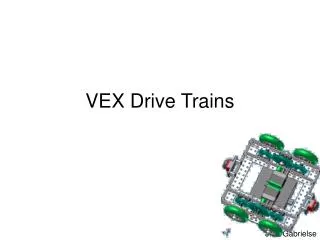
LESSON 07 • Drivetrain Design • The most basic, multi-functional competition robot Drivetrain design consists of: • A rectangular Chassis (the structure of a mobile robot that holds wheels, motors, and/or any other hardware used to make up a Drivetrain) • Two Motors • Four Wheels • Gears transmitting Power from the Motors to all Wheels. The Clawbot IQ Robot Base is one example of this that you can build. From this most basic Drivetrain design to those that are larger, don’t transmit power to some wheels, have different dimensions, use more motors, are made up of different shapes, or use a different number of or different type/size of wheels, you should always be aware of a property known as Turning Scrub.
LESSON 07 Turning Scrub is the friction that resists turning. This friction is created from the wheels dragging sideways on the ground as a robot (or other mobile vehicle) turns. The greater the Turning Scrubin a Drivetrain, the harder it is for a robot to turn. Turning Scrub in a basic Drivetraincan be easily managed and minimized in two ways: 1. Make sure that the Wheelbase (distance between Drivetrain wheels) is wider (side-to-side) than it is long (front-to-back):
LESSON 07 2. Use different wheel and/or tire types to reduce the friction of Turning Scrub: Try building the example Drivetrainsabove to see the Turning Scrub effect!
LESSON 07 In mobile and competition robotics an Object Manipulator is a mechanism that allows a robot to interact with objects in its environment. There are three basic categories of Object Manipulators: Plows, Scoops, and Friction Grabbers. Plows The first Object Manipulator category applies a single force to the side of an object. Plowsmove objects without actually picking them up and are by far the easiest manipulator type to design and build. Scoops The second Object Manipulator category applies force underneath an object such that the object can be elevated and carried. Once an object is on a Scoop, it can be lifted and lowered relying on gravity to keep the object on or in the Scoop.
LESSON 07 Friction Grabbers The third Object Manipulator category applies a force to an object in at least two places, allowing the object to be pinched or grabbed. Thus, Friction Grabbers have the ability to hold objects securely and are generally the manipulator type that provides the most control over objects. The most common form of this manipulator type is a pinching claw.
LESSON 07 Before discussing Lifting Mechanisms, it’s important to know what a Degree of Freedomis. A Degree of Freedom refers to something’s ability to move in a single independent direction of motion. To be able to move in many directions means something has many Degrees of Freedom. Moving up and down is one degree of freedom, moving right and left is another; something that can move up/down and left/right has TWO Degrees of Freedom. A Lifting Mechanism is any mechanism designed to move to perform tasks and/or lift objects. With that understood, let’s look at Lifting Mechanism types. In competition robotics, there are three basic types of Lifting Mechanisms: Rotating Joints, Elevators, and Linkages.
LESSON 07 Rotating Joints The most frequently used lifting mechanism in mobile and competition robotics is a Rotating Joint. Rotating Joints are the simplest Lifting Mechanisms to design and build. In VEX IQ, using a shaft and gears quickly creates an arm that will rotate and lift. This type of Lifting Mechanism moves on an arc, changing the distance any manipulated objects are from a robot base and changing the orientation of those objects (relative to their environment) on the way up.
LESSON 07 Elevators Another lifting mechanism used in mobile and competition robotics is an Elevator. While not as common as the Rotating Joint, the Elevatoruses linear (straight line) motion to lift straight up. In VEX IQ, one way elevators can be built is with Rack Gears and Linear Sliders, both sold as part of the Gear Kit. This type of Lifting Mechanismmoves straight up and down, keeping the distance between any manipulated objects and the robot base, as well as the orientation of those objects, consistent on the way up.
LESSON 07 Linkages Linkagescan also be used to build Lifting Mechanisms. Linkages consist of a series of rigid bodies called links, connected together by freely rotating joints. Linkagesconvert an input motion into a different type of output motion and can be very consistent. For example the input motion could be a Rotating Joint, but the Linkagecould produce Elevator-like output motion. In VEX IQ, combinations of different-sized beams, shaft and/or connector pins can be used to construct a Linkage. One of the simplest and most common linkage types is the Four-Bar Linkage. This is a linkage system that provides a wide variety of motions depending on its configuration. By varying the length of each link, one can greatly change the output motion. The most basic type of Four-Bar Linkageis one where link pairs are equal length and parallel to each other.
LESSON 07 Rotating Joint, Elevator, or Linkage? Elements to consider when deciding what type of Lifting Mechanism is best for • Elevation Required – How high do you have to lift? • Object Orientation – Do the objects you are lifting have to remain in a certain orientation? • Size Limitations – Are there design or environmental limitations to your robot’s size? • Complexity – How many degrees of freedom are desired? What type of hardware is required? • Motors Required – Do you have enough? Is the total number limited?
LESSON 07 PLENARY As a class, let us consider the following questions?A. What is an Actuator? B. What does a DC motor do? C. Can you name the 2 types of gears and object manipulators?D. What is turning Scrub and how is it caused?
SUMMARY Learning objective: Learn about DC Motors. Learn about and apply knowledge of Gear Ratio. Learn about Drivetrains. Learn about Object Manipulation. Learn about lifting mechanisms. • Today you have: • Learnt about DC Motors. • Learnt about and apply knowledge of Gear Ratio. • Learnt about Drivetrains, object manipulation and lifting mechanisms .