Download
1 / 47
480 likes | 593 Views
Building a RTOS for MPSoC Dataflow Programming. Osman Salem, Alexey Guerassimov , and Ahmed Mehaoua University of Paris Descartes – LIPADE Division of ITCE, POSTECH, Korea Anthony Marcus and Borko Furht ,

E N D
Building a RTOS for MPSoCDataflow Programming Osman Salem, Alexey Guerassimov, and Ahmed Mehaoua University of Paris Descartes – LIPADE Division of ITCE, POSTECH, Korea Anthony Marcus and BorkoFurht, Department of Computer and Electrical Engineering and Computer Science, Florida Atlantic University Jonathan David 2013 IEEE International Conference onCommunications, pp.4373,4378, 9-13 June 2013
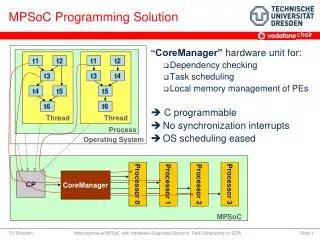
The Need for Improvement • Multiprocessor System-on-Chip (MPSoC) designs are becoming standard in high performance DSP applications • Zync • Altera SoC • ZigBee • Thus, being able load balance and make efficient use of parallel resources is of increasing importance • Need for a tool to ease MPSoC programming
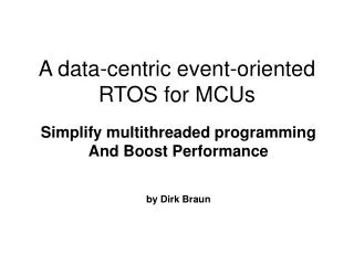
The Solution • Design of a real-time operating system capable of effectively managing resources • Use of dataflow models shown to favor parallel algorithms • Favors data locality • Reduces multi-core scheduling constraints to data dependencies • Use of data flow graphs instead of thread declarations • Execution handled by MPSoC RTOS • Frees programmer from creating program primitives for task migration and synchronization
How does it work? • Partitions each application between available cores • Parallelism of each application is stated inside of a dataflow graph • Ensures good load balancing • Reduces computation latency • MPSoC RTOS reuses C/C++ code for its actors • Combines it with parameterized dataflow coordination language
Dataflow Model • Well suited for applications based on a loop • Telecommunications • Video processing • Describes computation by splitting loop into actors • Data exchanged through inputs/outputs only • State of actor is not shared • Flow model is created before execution, and can be totally reconfigured once before starting a new executions
Dataflow Model • Graph is represented by C++ objects • Compile within dataflow management module • On each OS clock tick: • Dataflow graph parameterized • Temporary graph of execution obtained • Each actor gets an RTOS task
Dataflow Graph Management • An expansion is performed on the application • Dataflow graph transformed into temporary graph • Each actor is executed only once in an iteration • Temporary graph is dependent on parameter values that change between each iteration
Dataflow Graph Management • RTOS task is created for each actor • Tasks then scheduled on the cores of the MPSoC device • Alternate algorithms for dataflow management can be created, only restriction is that a dataflow graph can be produced
Scheduling • Split into two phases • Master/Slave Phase • Symmetric Phase
Master/Slave Phase • Master core executes dataflow graph management, posts actors to the slave cores, and finally posts actors to itself • Each core has a 1-place queue to receive an order to execute a task • Message contains address of the task in shared memory • Input/output buffer information contained • After first task dispatching is complete, all cores become pairs and the symmetric phase begins
Symmetric Phase • Each core can access the schedule function • Mutex semaphores provided within library • Highest priority task executed first • Scheduler called in two scenarios • Execution of task is preempted by higher execution task • Task execution completes • If a core has no remaining tasks, the scheduler saves the current task’s context state and the core returns to its private memory
Results • OS takes up a lot of space (more than 50%)! • Due to the size and task stacks allocated by kernel
Results • Different number of actors for each iteration
Results • Performance improves with number of cores • Definite diminishing returns • Shared memory accesses creates a bottleneck
Shortfalls of the Study • Study is focused primarily on signal processing • Does not mention how the dataflow graphs are created, or how much time it takes (only mentions it falls within parameters for the tested algorithm) • Does not mention how much of a bottleneck is created by using one core as a master • No comparison against traditional/hand coded method
Conclusions • Proposed MPSoC RTOS can ease difficulty of programming for modern day DSP applications • Increase in performance with number of cores • Bottleneck with increased memory accesses • Large amount of memory occupied by proposed OS • Actors can be written in C or C++ • Where is the competition? • Can’t compare, does it result in a trade-off?
R3TOS: Reliable Reconfigurable Real-Time Operating System Mai Abdelhakim, Leonard E. Lightfoot, Jian Ren, Tongtong Li Department of Electrical & Computer Engineering, Michigan State University Air Force Research Laboratory, Wright-Patterson Air Force Base Jonathan David 2013 IEEE International Conference onCommunications, pp.1720,1724, 9-13 June 2013
The Need for Improvement • FGPAs provide promising possibilities for the future as semiconductor manufacturing reaches its physical limits • Obtain best performance per transistor count per unit of consumed energy • Increase in reliability • High amount of computation in given space and time
The Solution • Use of online specialization • Intelligent reuse of resources in the FPGA • Architecture kept fault-free by reconfiguring around damaged areas of the chip • Maintain a “software look and feel” to avoid a collapse in productivity and cost • Satisfy requirements of high-performance, real-time, fault-tolerance necessary in applications
Fundamental ROS Services • Software OS augmented with functions to manage reconfigurable hardware • Task loading • Memory management • Scheduling and allocation • Communications • Hardware hardware • Hardware software • Input/output • Accessible through AP, with runtime support
R3TOS Foundations • Resource reusability and computation ephemerality • Intensive use of fine-grained reconfiguration • Aims to keep resources available to any incoming task at any time • Circuits configured when required, then removed • Clock distribution wires • Task communication channels • Resources can be used for either computation or communication purposes
R3TOS Foundations • Control logic to drive tasks is attach to their own circuitry, as opposed to predefined reconfigurable slots with fixed control logic and comm structures • Self-contained, closed structures • Fully relocatablewithin FPGA
Task Control Logic (TCL) • Includes input data buffer, output data buffer, and hardware semaphore enable/disables computation • Provides means to virtually lock physical data and control data of hardware tasks to logical positions in the configuration memory of the FPGA • Frees the allocation of a task from being constrained by communication interfaces during design time • TCLs are accessible through the configuration interface of whichever memory position they are mapped to
TCL Advantages • Number of tasks executed concurrently only limited by resources on the FPGA • Tasks can be allocated around damaged resource • Increased computation density • Complexity of allocation algorithms reduced • No need to be aware of underlying implementation-related irregularities in the reconfigurable area • No need to preserve static routes
TCL Advantages • Tasks can be de-allocated quickly using multiple frame write configuration commands • Simply blank an entire region • Each task can be clocked at its highest frequency, rather than running entire fabric on same clock • Device ages uniformly
The Downsides • Bottleneck from the internal configuration access port leads to significant time overheads • Configuration of a hardware task delays its execution • Configuration of on-demand communication channels incurs an overhead greater than the time needed for created a virtual connection through a network-on-chip
Computing Model • Task definitions and interactions described using parallel software syntax (POSIX Pthreads) • Body of some tasks implemented in hardware • R3TOS addresses two main hardware tasks: • Data-stream processing, to be used with data-intensive applications with regular dependencies • Hardware-acceleration tasks • User relies on the R3TOS API to program their reconfigurable application • Execution of tasks controlled by main CPU
Computing Model • The software microkernel (SWuK) interacts with the hardware microkernel (HWuK) • SWuK schedules/executes software tasks and forwards hardware tasks to the HWuK • Hardware related services offered in the API are determined by the HWuK • Scheduler server to schedule hardware tasks • Allocator server manages FPGA resources • Configuration manager to translate high-level operations into reconfiguration commands for the FPGA
General Architecture • A little bit complex, probably
General Architecture • Three main parts • HWuK • Main CPU • Memory
Hardware Microkernel • Each component is implemented separately to allow for parallelism in the HWuK processes • Allows for low runtime overhead and area overhead • Main core of all HWuK components is the PicoBlaze • Requires only 96 slices • HWuK components mastered by scheduler • Allocator and configuration manager act as slaves • Communication between components managed by a very strict set of rules, overseen by two monitors (to detect malfunctions)
R3TOS Main CPU • Xilinx on-chip processor (32-bit MicroBlaze soft-core) is used as main CPU • Timer and interrupt peripherals included to expand functionality • Program executed by CPU is held in directly accessible program memory (BRAMs in FPGA) • Interfaced with the HWuK based on interrupts and shared memory
Memory • Bitstream memory and main memory held on one external chip • Data and code segments of software tasks • Data segments and bitstreams of hardware tasks • Bitstreams of the data relocating tasks • Lowest part of memory contains a pointer table, allowing the HWuK to know the exact location of each task bitstream
Shortfalls of the Study • Has yet to be seen if the implementation is practicalfor most applications • Can’t be seen how execution times are effected • How difficult is coding? • Energy usage of device? • That’s is about it…the paper is pretty solid
Conclusions • R3TOS allows for a viable, reconfigurable, real-time operating system • Many advantages gained by freeing hardware from static communication lines • Better able to use resources • Even wear over device • Possible performance increases • Viability of design must wait for practical implementation, currently only proof of concept