Download
1 / 46
460 likes | 469 Views
Survey of the EURISOL activities developed in SPhN. D. Ene CEA-Saclay, IRFU/SPHN, F-91191 Gif-sur-Yvette, France. EURISOL: next-generation ISOL facility.

E N D
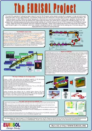
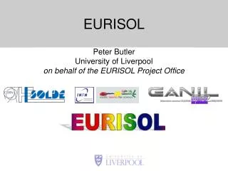
Survey of the EURISOL activities developed in SPhN D. Ene CEA-Saclay, IRFU/SPHN, F-91191 Gif-sur-Yvette, France
EURISOL: next-generation ISOL facility The study will address the major technological problems which are expected to arise in the creation of a facility able to provide exotic ions in quantities which are orders of magnitude higher than those currently available anywhere else in the world CEA Saclay, 30.01. 2009
EURISOL conceptual lay-out Task#5 Shielding & Safety estimates along the facility Task#11 Beam Intensity Calculations CEA Saclay, 30.01. 2009
EURISOL MMW target concepts Hg converter and secondary fission targets First version of design CEA Saclay, 30.01. 2009
Goals: • Developing an approach used to support waste analysis for 4 MW power target shielding; • Classification of the radioactive wastes based on IAEA clearance concept for bulk shielding of MMW power target. CEA Saclay, 30.01. 2009
UCx p (1GeV; 4 MW) Hg Procedure (1): 1.Radiation transport simulations • - Model: (INCLL4 + ABLA) for Yn & (ISABEL-RAL) for3H production • - Geometry model used in simulations: - Source: p 1GeV | Gauss (s=1.5cm) • - Material: AISI304LN stainless steel, r=7.92 g cm-3; Ordinary concrete, r=2.3 g cm-3| with 0.4% H content. - Biasing method: • Weight window mesh-based variance technique • Calculations for forward and perpendicular directions 2. Activation of target shielding -Materials description; -Irradiation scheme: 40 years irradiation at 2.28 MW; 0, 0.27, 3, 10, 25, 100, 300 and 1000 years decay times CEA Saclay, 30.01. 2009
Procedure (2): 3. Clearance indexes determination CI= (IAEA TECDOC 855 recommendations) Ai= specific activity of each component in the material; Li= Clearance limit (Bq/g) derived to meet individual dose criterion of 10mSv/y -Litaken fromIAEA Safety Guide Report RS-G-1.7 (2004) -Licalculated using: Eg, Eb from FENDL D.2.0; ALIing, inh from ICRP72 CI calculated in forward and perpendicular locations 3. Clearance indexes determination CI = Ai= specific activity (Bq g-1)of each component in the material; Li= Clearance limit (Bq g-1) derived to meet individual dose criterion of 10 mSv y-1 -Li taken from IAEA TECDOC 855 (1996) & Safety Guide Report RS-G-1.7 (2004) -Li calculated using: Eg, Eb (keV) effective emission energy from FENDL D.2.0; eing, inh (Sv/Bq) =committed effective dose equivalent from inh, ing from ICRP72 IAEA Safety Guide SS No.111-G1 (1994) CI calculated in forward and perpendicular locations CEA Saclay, 30.01. 2009
Procedure (3): 3. Clearance indexes determination CI= (IAEA TECDOC 855 recommendations) Ai= specific activity of each component in the material; Li= Clearance limit (Bq/g) derived to meet individual dose criterion of 10mSv/y -Litaken fromIAEA Safety Guide Report RS-G-1.7 (2004) -Licalculated using: Eg, Eb from FENDL D.2.0; ALIing, inh from ICRP72 CI calculated in forward and perpendicular locations 4. Waste classification using clearance concept (IAEA Safety Guide SS No.111-G1 (1994)) LL -LILW =Low and Intermediate Level Wastes –Long Lived; SL-LILW =Low and Intermediate Level Wastes –Short Lived; EW = Exempt Wastes -CI < 1 =>EW; -CI > 1 : 1. CI of nuclides with T1/2> 30 years >1 -> LL-LILW 2. CI of nuclides with T1/2>30 years <1 -> SL-LILW Entire radioactivity map and corresponding CI deduced using total flux ratio scaling in: 1. 10 cm X 10 cm mesh grid 2. 1 m thick shield layer -Allocation to a waste category; -Summation of activities and masses in each waste category CEA Saclay, 30.01. 2009
Method / Tools: Neutron flux in ith cell ⇨The neutron flux is assumed to be constant over the irradiation period and not being modified by the irradiated medium Geometry and materials description MCNPX.2.5.0 Residues in ith cell Irradiation Scheme- DCHAIN-SP-2001 CL Library (ANITA-2000*+update IAEA RS-G-1.7, 2004) Activation products & CI | < T1/2 > Neutron flux map Activation map Activities & masses waste categories CEA Saclay, 30.01. 2009
Unconditional Clearance Index Representative locations| 0 degree Representative locations| 90 degree Concrete layers > 770 cm below exemption limit Concrete layers> 560 cm below exemption limit CEA Saclay, 30.01. 2009
Zone 2 | 90 deg. Zone 1 | 0 deg. Shielding activation 10 years After 100 days 1 MBq g-1 < A < 5GBq g-1 1 kBq g-1 < A < 1MB g-1 1 Bq g-1 < A < 1kBq g-1 A < 1Bq g-1 1. Thick layers -1m- 2. Fine meshes –Tmesh grid Activity within cutting plans: -activity at representative location – entrance -ratio of total flux –scaling factor 100 years 1000 years CEA Saclay, 30.01. 2009
Waste categories| Mesh tally approach ~204 t of steel LL-LILW; ~10528 t concrete: ~ (0.7->0.5)% mtotal_concrete LL-LILW. ~ (80 -> 99.5)% mtotal_concrete EW CEA Saclay, 30.01. 2009
Waste categories| Thick layer approach ~204 t of steel LL-LILW; ~10528 t concrete: ~ 6.2% mtotal_concrete LL-LILW. ~ (42 -> 94)% mtotal_concrete EW CEA Saclay, 30.01. 2009
SUMMARY / CONCLUSIONS disposed of as permanent radwastes • At shut-down of the facility for the bulk shielding of the 4MW target: ~ 204 tonnes of steel => ~ 73 tonnes of concrete => ~ 1823 tonnes of concrete => interim storage ~ 8632 tonnes of concrete => declassified (NAW) • Precision in activity estimates may have important consequences upon derived level of radioactivity of materials and their classifications as `wastes;` • Method developed here will be used for the shielding of MAFF-like target concept; • Air activation in the shielding gap; • Source term for contaminant transport • Classification of wastes arising from the shielding of the MMW target has a strong impact on the decision and the strategy to be adopted for dismantling and final storage of the EURISOL facility; • Accurate estimation of the activity inside the shielding is a very important issue having further consequences overall timescales and costs of the entire installation. CEA Saclay, 30.01. 2009
POSTACCELERATOR design concept | Goals • Tunnel shielding configuration • Thicknesses of shield blocks • Induced radioactivity & dose rates for planning interventions inside the tunnel • Radiation environment characterisation • Production of contaminants • Source term for airborn transportation CEA Saclay, 30.01. 2009
209 m Without stripper 44 m Nb + (Fe or Al) + Cu + He LINAC 10-5 - 10-4/m 150 MeV/u 0.585 MeV/u Experimental areas and beam dump 21.3 MeV/u Schematic view of the two options for the EURISOL LINAC-variant 1&2 Experimental areas and beam dump 1 10 m 102 m 44 m With stripper Stripper Nb+(Fe or Al)+Cu+He Nb+(Fe or Al)+Cu+He Experimental areas and beam dump LINAC LINAC 60 % in the first 5 m 10-5 - 10-4/m 10-5 - 10-4/m 0.585 MeV/u 150 MeV/u 2 21.3 MeV/u Experimental areas and Beam dump Variant #1 Variant #2 Cu + Fe + slits (2mm W, 1cm Cu) Foil : C 3 mg/cm² Energy gradient for 132Sn25+ Energy gradient for 132Sn25+ CEA Saclay, 30.01. 2009
POSTACCELERATOR design concept / Shielding design requirements • Linac is placed in unerground concrete tunnel; • Beam fcailities are shielded with movable shielding blocks; • Beam dumps are locally shielded. CEA Saclay, 30.01. 2009
PROMPT RADIATION: Assumptions & Approach* Accidental loss Continuous loss A shield designed for a continous beam loss of 10-4 m-1 (point loss of 6.25*109 ion s-1 ) during the routine operation is also adequate for an accident loss of the full beam at a localised point, providing that the linac cutoff time is less than 1s. * A. Fasso, K. Göebel et all, Shielding against high energy radiation, Nuclear and Particle Physics, Vol 11, (1990) **S. Agosteo, M. Silari, CERN Note 088/ TIS-RP/TM/2001-028 A full beam loss at a localised point must not give rise to a H*(10) > 100 mSv/h outside the shielding and the beam has to be swithed off within a time short enough that the H*(10) from this accident condition remains negligible. CEA Saclay, 30.01. 2009
2.8 W 10 W 15 W 19.8 W 6 W 10-4 m-1 => <= 10-4 m-1 => 44 m 165 m beam dump RFQ SIL(1) SIL(2) Experiment rooms Experiment rooms 0.585 MeV/u 21.3 MeV/u 150 MeV/u PROMPT RADIATION: Schematic diagram of SIL#1 shielding Uncontrolled beam loss of 10-4 m-1 staff public Dump / 2.8kW | 165 | 230 Dump / 19.8kW | 385 | 500 *V1, Unitary Volume (corresponding to a width = 1m) CEA Saclay, 30.01. 2009
RFQ 0.585 MeV/u Experiment rooms Experiment rooms PROMPT RADIATION: Schematic diagram of SIL#2 shielding Uncontrolled beam loss of 10-4 m-1 7.92 W 2.8 W 2.4 W 4 W 6 W 1.68 kW 10-4 m-1 => <= 10-4 m-1 => 44 m 102 m beam dump SIL(1) Stripper SIL(2) 21.3 MeV/u 150 MeV/u * Correspond to a width = 1m CEA Saclay, 30.01. 2009
LINAC Shielding: Conclusions (1) • The proposed thicknesses of the shielding guarantee an integrated dose bellow the acceptable limit with sufficient margin both at normal operation and accidental situations assuming that the beam cut off 1 s is feasible • From the shielding safety point of view, SIL#2 is more advantageous variant since it requires nearly 2 times less of the shielding compared to SIL#1 • Placing the LINAC in a designated controlled area (dose below 10 μSv h-1) might reduce the total shielding by another factor of 2 • A safety operation domain (energy range & beam intensities) has to be established to account for other ion species. CEA Saclay, 30.01. 2009
Neutron flux in ith cell ⇨The neutron flux is assumed to be constant over the irradiation period and not being modified by the irradiated medium RESIDUAL RADIATION: Method Geometry and materials description PHITS Residues in ith cell Irradiation Scheme- DCHAIN-SP-2001 12d irradiation Activation products & Photon sources MCNPX H*(10) CEA Saclay, 30.01. 2009
RESIDUAL RADIATION: Total activity / H*(10) inside the tunnel Points -> contact Lines -> 1m distance 21MeV/u 150MeV/u CEA Saclay, 30.01. 2009
Conclusions (2) • Residual activation field inside the tunnel are arising mainly from copper structure activation in the high energy zone of the accelerator, while in the accelerator low energy zone the ion implantation is the most significant contributor; • In the high energy zone of the LINAC continuous accessibility inside the tunnel in the beam-off stage is possible only after five days cooling time. However, if the intervention is required earlier, an occupancy factor of minimum 570 hours/year allows to meet the constraint of 20 mSv y-1; • Contact dose rate values significantly higher than the limits show that a remote handling for the dismantling of certain components is necessary. The accelerator structure in the high energy zone even after one month cooling time would contribute to the contact dose higher than 1 mSv h-1; • Definition of the intervention procedure is required. To protect the personnel during the handling operations the access and transportation paths should be set-up and a hot cell might be necessary to be included in the facility lay-out; • The air activation results may be used to derive the air change rate inside the tunnel and released source term required for further assessment of the airborne radionuclide environmental impact. CEA Saclay, 30.01. 2009
Source Term for contaminant transport Specific activity [Bq cm-3] in first 100 cm of soil/groundwater surrounding the concrete wall after 40 y of continous irradiation Per year in a volume of soil of 1.672*109cm3 5.265*104 Bq < 1012 Bq --LIMIT* 1.301*104 Bq < 105 Bq --LIMIT* Transport of radioactive species into the ground does not represent a hazard for the population Real evaluation to be done after the site will be chosen *IAEA TECDOC-1000, 1998,Clearance of materials resulting from the use of radionuclides in medicine, industry and research. CEA Saclay, 30.01. 2009
General conclusions • Analysis of the possibilities to reduce the shield thicknesses in compliance with ALARA principle has to be done; • Maintenance operations inside the tunnel have to be planned; • A ventilation systemin the tunnel might be necessary; • Several equipments and material should to be disposed of as radioactive wastes; • Shielding design is adequate from the point of view of the environmental impact CEA Saclay, 30.01. 2009
Beam Dump | Goals • Preliminary analysis of a beam dump model -neutronics; • Induced radioactivity; • Required shielding. CEA Saclay, 30.01. 2009
Graphite (1.84g/cm3) Copper + 10% water Iron shield Beam 5o 8 cm 16 cm 40 cm 100 cm Design of the BEAM DUMP* 132 Sn 25+ Beam power = 19.8 kW (150 MeV/u) Beam size σ = 2 mm Dump core under vacuum or inertial gas !!! At the limit of the safety operational conditions * Beam catcher FAIR Super-FRS | courtesy of H. WEICK (GSI) CEA Saclay, 30.01. 2009
Neutron flux in ith cell ⇨The neutron flux is assumed to be constant over the irradiation period and not being modified by the irradiated medium RESIDUAL RADIATION: Method Geometry and materials description PHITS/ MCNPX2.6.e Residues in ith cell Irradiation Scheme- DCHAIN-SP-2001 3h irradiation Activation products & Photon sources MCNPX H*(10) CEA Saclay, 30.01. 2009
Design of the BEAM DUMP: Activation Steel | dominant radionuclides Copper | dominant radionuclides CEA Saclay, 30.01. 2009
beam concrete void concrete / steel soil BD | Shielding design: thickness of the lateral wall CEA Saclay, 30.01. 2009
Beam Dump: Conclusions • A preliminary analysis shows that the beam dump wedge shape with 40 cm graphite core and 100 cm iron shield might be a solution for the specific case; • A kicker magnet 5 m long will be necessary to dilute the beam spot on the beam dump in order to assure safe operating conditions; • Direct human access for the beam dump maintenance is not allowable; • Two possible solutions for the beam dump lateral shielding were preliminary evaluated. CEA Saclay, 30.01. 2009
Experimental Hall | Goals • Sizing of the shield; • Management of the access to the controlled areas inside experimental halls. CEA Saclay, 30.01. 2009
Experimental Hall: parameters Reference parameters of the target rooms in the experimental hall of EURISOL postaccelerator needed for shielding & safety estimates *- conservative simplified geometry Operation scenario: realistic = 12 days of irradiation conservative = 90 days of irradiation with subsequent cooling time of 120 days CEA Saclay, 30.01. 2009
Parameters / Models • Physics parameters used in PHITS simulations: • JQMD model • Source: 132Sn; Gauss (s=2mm) • Biasing method: IMPORTANCE • HALL wall: Geometry : • Shielding Design @ beam dump load 19.8 kW(150 MeV u-1, 6.24*1012 pps) Material: • Ordinary concrete, density=2.3 g cm-3|with 0.4% H content • Iron • (Iron + concrete) composite shielding CEA Saclay, 30.01. 2009
Air 10cm Al 132Sn 6cm 16cm 25cm Ge Parameters / Models • Residual field (PHITS & DCHAIN) PHITS geometry model CEA Saclay, 30.01. 2009
PROMPT FIELD: Pb target comparison (2) model: 132Sn + Pb target AD* 10 mg cm-2 * Active Beam Dump 12 days irradiation 1 mg cm-2 Neutron flux axial profile -on beam direction Nuclear reactions (star density) 10mg cm-2target =>worst case for the residual activation 1mg cm-2 target => worst case energy depositon BD & H*(10) CEA Saclay, 30.01. 2009
Design of the BEAM DUMP | dE/dV Design of the Active Dump to be optimised ADC = Active Beam Dump | conic opening ADC | (150 MeV u-1, 6. 2*1012pps) 132Sn +Pb (1mg cm-2) PDW = Passive Beam Dump | wedge opening Dump core under vacuum or inertial gas PDW | 19.8 kW (150 MeV u-1 , 6. 2*1012pps) 132Sn CEA Saclay, 30.01. 2009
forward concrete void concrete / steel soil air Ge Pb 1 mg cm-2 BD Shielding design | neutron H*(10) forward PD shielding beam PHITS model forward ~ 60 cm from the hot spot Neutron H*(10) results AGATA equipement forward air attenuation scaling factor ? CEA Saclay, 30.01. 2009 H*(10) profiles in the forward plan
kicker magnet Beam dump area 21.3 MeVu-1 0.585 MeV/u 19.8 kW 2.8W 10W 6 W 15 W 19.8 W <= 10-4 m-1 => 44 m <= 10-4 m-1 => RFQ 165 m 150 MeV u-1 . Experiment rooms to be defined POSTACCELERATOR Shielding design: thickness of the wall CEA Saclay, 30.01. 2009
In target yields estimates Direct target Fission targets CEA Saclay, 30.01. 2009
In-target yields for RIB production Direct target All configurations studied CEA Saclay, 30.01. 2009
In-target yields for RIB production Direct target CEA Saclay, 30.01. 2009
In-target yields for RIB production Direct target Example of Optimization CEA Saclay, 30.01. 2009
RIB extraction line Reflector Moderator Fission target Mercury target Proton beam Iron shielding Barite concrete shielding MMW fission target: Parameters / Model • Parameters : Geometry : • Last design variant (L. Tecchio) able to accommodate 30kW load heat • Volume = 181cm3 (Rext=1.75cm, Rint=0.4cm, H=20cm) Material: • graphite + U, density=1.16g/cm3, • mass U=10g | mase rate: U/C=1/20 (MKLN) • Physics parameters used in MCNPX simulations: • Source: proton; E=1GeV; Gauss (s=1.5cm) • Model: CEM2k • Operational temperature: 293K CEA Saclay, 30.01. 2009
Preliminary results 235U(99.99%) H2O: moderator/BeO: reflector Total Flux: 7.14*1013 n cm-2 s-1/1mA Total Fission Rate: 1.98*1014 fiss s-1/1mA Fission Rate –energy distribution Fission Yields | selected products 232Th Fe: moderator/Fe: reflector Total Flux: 7.15*1013 n cm-2 s-1/1mA Total Fission Rate: 4.19*1010 fiss s-1/1mA Fission Rate –energy distribution Fission Yields | selected products CEA Saclay, 30.01. 2009