Download
1 / 42
420 likes | 550 Views
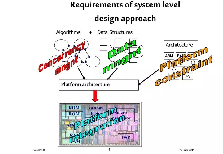
Algorithms. +. Data Structures. Architecture. ARM. RAM. ROM. IP 1. IP 2. Platform architecture. ROM. custom logic. micro processor. ROM. MMU. Platform integration. RAM. DSP. RAM. Requirements of system level design approach. Data mngnt. Concurrency mngnt. Platform

E N D
Algorithms + Data Structures Architecture ARM RAM ROM IP1 IP2 Platform architecture ROM custom logic micro processor ROM MMU Platform integration RAM DSP RAM Requirements of system level design approach Data mngnt Concurrency mngnt Platform constraint
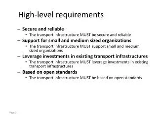
Current challenges and solutions • System Specification and System-level Refinement with Exploration Support (algorithm design level, concurrent task level, system timing simulation) • Data Transfer and Storage Exploration for Massive Real Time Data Manipulation (dynamic memory mngntstatic transfer and storage, address generation) • Co-Design for Heterogenous Implementation Paradigms (refinement from unified HW/SW model,RTOS modeling, complete system simulation) • RF front-end exploration (fast mixed-signal co-simulation, chip-package co-design, noise coupling)
Task vs Array data vs Instr level issues Optimized system specification Task2 Task1 Task level issues Task3 Task-level system architecture Array data level issues Array-level system architecture Proc2 Proc1 Instr.-level issues Arithmetic + local control + address issues Proc3 Proc.-level system architecture
Proc1 Proc2 Proc3 Concurrency versus DTSE issues Background memories Optimized system specification Data transfer and storage exploration issues DTSE optimized specification Concurrency issues Arithmetic + local control + addressing Proc.-level system architecture
J c o l u m n s I r o w s Why fix data storage/transfer before concurrency mngnt issues? Recursive image processing algorithm on local neighbourhoods: (i : 0 .. I-1 ) :: (j : 0 .. J-1 ) :: img[i][j]= f(img[i][j-k], old_img[i][j]);
J c o l u m n s 2 I 14.4mm (0.7um) r o w s Why fix data storage/transfer before concurrency mngnt issues? For given speed-up M: minimally M data-paths for f() Unrolling i loop (limited by I): M J-word double-buffered FIFO's
J c o l u m n s I r o w s Why fix data storage/transfer before concurrency mngnt issues? Unrolling j loop (limited by k): M - 1 buffer reg (i : 0 .. I-1 ) :: (j : 0 .. (J div 2)-1 ) :: . begin .img[i][2j-1]= f(img[i][2j-k-1], ... old_img[i][2j-1]); . img[i][2j]= f(img[i][2j-k], ... old_img[i][2j]); . end;
Binary Tree (BT) key data Concurrent OO spec Free Blocks key key data data Sub-pool per size Task concurrency mgmt SW/HW co-design processor Dynamic Memory mem mem mem Data Allocation Types Assignment ASU ASU controller Virtual SW design flow HW design flow Memory Memory Mgmt Mgmt Unit Global data management design flow for dynamic concurrent tasks with data-dominated behaviour Data Type Refinement Physical memory mgmt Address optimization
Data Management Flow Dynamic Data TypeTrafo & Refinement DDT ConcreteData types Dynamic Data Type Explor. Dynamic memory mgmtRefinement VirtualMemorySegments Physical memory mgmtRefinement PhysicalMemories Physical Memory Mngnt.
Client MainMemory LocalLatch LocalLatch LocalSelect LocalSelect bank1 bankN 128 - 1024bit bus Client CacheandBankcomb. GlobalBankSelectControl ctrl data addr Wide word Burst mode Data-transfer and data-storage bottlenecks: SDRAM access
Client MainMemory MainMemory Data-paths 16kBN-port SRAM 1MB1/2-portSRAM regf 256 MB (S)DRAM L1 cache Processors L2 cache Many cache missesPage Loading Data-transfer and data-storage bottlenecks: cache misses
Data-transfer and data-storage bottlenecks: system bus load Diskaccess bus Main system bus L2 bus Data paths L1 cache L2 cache MainMemory Hard disk System chip OtherSystemResources OtherSystemResources
Locally optimized Image Proc System Globally optimized => exploration! Standard Subsystem New subsystem : resembles a complex detailed solution standard solution subsystem locally optimized but needs small by expert adaptations Buffer Buffer E.g.: 2D convolution E.g.: quadtree coder E.g.: DCT for specific coder Multi-processor System Design
(multi-media) = Power volcano processor trend Traditionalcompiler boulevard Multi-media platform city Traditional architecture city Cobblestone bypass road (requires paving) Platform design requires change Application engineer
Ad-Hoc Design: Backtracking ? System Specification ? ? ? ? ? ? ? ? ? ? ? ? ? ? Memory Organizations ? ?
? ? ? ! ? ? ! ? ? ? ? ! ! ? ? ? Systematic System Exploration System Specification Memory Organization
Data Transfer & Storage Exploration (DTSE) Principles Local Latch 1 + Bank 1 Processor Data Paths L1 Cache L2 Cache Cache & Bank Recombine Local Latch N + Bank N Chip Off-chip SDRAM
Data Transfer & Storage Exploration (DTSE) Principles Local Latch 1 + Bank 1 Processor Data Paths L1 Cache L2 Cache Cache & Bank Recombine Local Latch N + Bank N Chip Off-chip SDRAM ANALYSIS !
4 Avoid N-port Memories 1 Reduce redundant transfers 2 Introduce Locality Main Data Transfer & Storage Principles 3 Exploit memory hierarchy Local Latch 1 + Bank 1 Processor Data Paths L1 Cache L2 Cache Cache & Bank Recombine Local Latch N + Bank N Chip Off-chip SDRAM 6 Exploit limited life-time and data layout freedom 5 Meet real-time constraints
Fast implementation with tools Time - Efficient System Exploration Design Flow Initial System Specification design alternatives System-level Feedback ? ? Accurate cost figures to guide decision
Initial description Cavity detection application:medical imaging Every function computes new matrix information from the output of the previous step. The new value of a pixel depends on its neighbors.
Conclusions for DTSE stage • Order of magnitude can be typically gained on system bus load| • As a result, also the energy consumption in the data memory hierarchy is reduced with about the same amount • Also the system performance (board level) is significantly reduced because of competing resources on these system busses • Penalty on code size is small (less than 20%) • Typically the pure CPU speed is improved IF there was a data transfer bottleneck that could not be “hidden” by overlapping the computation and communication in the original code (which was certainly so for the cavity detector)
Task- versus Proc./Instr-level: mapping Task2 Task1 Array Array Proc2 Proc1 Task3 Proc1 Proc2 Proc3
Pareto curves allow task trade-off decision: DAB illustration TASK-1 TASK-2 TASK-3 1000 12 15 y 8 10 g r e 500 n E 4 5 0 0 0 0.0 2.0 4.0 6.0 0 10000 20000 30000 40000 0 50000 100000 Execution time Execution time Execution time Mapped on two processors Source: Digital Audio Broadcast
Pareto curves allowtask trade-off decision TASK-1 TASK-2 TASK-3 1000 12 15 y 8 10 g r e 500 n E 4 5 0 0 0 0.0 2.0 4.0 6.0 0 10000 20000 30000 40000 0 50000 100000 Execution time Execution time Execution time Single proc. Large mem. overhead Source: Digital Audio Broadcast
Pareto curves allowtask trade-off decision TASK-1 TASK-2 TASK-3 1000 12 15 y 8 10 g r e 500 n E 4 5 0 0 0 0.0 2.0 4.0 6.0 0 10000 20000 30000 40000 0 50000 100000 Execution time Execution time Execution time Source: Digital Audio Broadcast
Cache Power 2 Main memory Power 1 Cache Size [ words ] 0 32w 64w 96w 128w 256w 512w Trade-offs in memory organisation(e.g. voice coder SW controlled cache) • Gain in power of additional factor 6 comparedto optimized (platform independent code) Relative power
Concurrent OO spec Task2 Task1 Task concurrency mgmt SW/HW co-design Task3 Memory organ. Unified model HW DSP uProc Partition Refine/compile HW-Ctrl uCtrl System control SW design flow HW design flow Transform Task schedule Allocate/assign Global concurrency management design flow for dynamic concurrent tasks with data-dominated behaviour Data Type Refinement Physical memory mgmt Address optimization
JPEG MPEG4 T4 T1 T3 T1’ T2 Why are Applications becoming more dynamic and concurrent? T1 The workload decreases but the tasks are dynamically created and their size is data dependent
ARM Processor 2 ARM Processor 1 Reduce global system energy by task scheduling + assignment (e.g. 2-processor approach ) TN1 TN2 TNn Vdd=1V Vdd=3.3V Codes’01, System Design Automation book Verlag’01
20M instr. 20 M TUs 400 mJ 90M instr. 180 M TUs 450 mJ 180 M TUs 70M instr. 70 M TU 1400 mJ 40M instr. 80 M TU 200 mJ 80 M TUs Tradeoff between time-budget and energy Processor 2 High speed Processor 1 Low Vdd Vdd=3.0V 20nJ/instr. 1TU/instr. Vdd=1.5V 5nJ/instr. 2TUs/instr. More TimeUnits More energy Tradeoff 1600 mJ 850 mJ
Non-optimal points x x x x Processor alloc/assign and scheduling alternatives For TNs in code version 1 Trade-off between time budget (period/latency) and cost (e.g.energy) leads to Pareto curves Cost TB6 TB5 TB4 TB3 TB2 TB1 Time
Not single working point but Pareto curves needed in global trade-off Energy (nJ) 3500 Both data transfer-storage and concurrency aspects have to be combined! 3000 2500 2000 1500 1000 500 0 0 50 100 150 200 250 Time budget (us)
Comparison of scheduling the original and transformed task-level descriptions Energy (nJ) original Transformed Time budget (us)
cost cost TF 1 Design-time Scheduling Design-time Scheduling TF 2 Run-time Scheduling time time 1 3 2 A B 1 A B 3 2 • Design-time scheduling: at compile time, exploring all the optimization possibilities • Run-time scheduling: at run time, providing flexibility and dynamic control at low cost as part of synthesized RTOS Overall solution: combination of complex design- and simple run-time schedulers Cases’00, ISSS’01,Design&Test- Sep.’01
task energy Energy task execution time task execution time Run-time: original Pareto point selection Application Task 1 application energy Task 2 time limit application execution time
task energy Energy task energy task execution time task execution time task execution time Run-time: one selection if new task enters Application Task 3 Task 1 Task 2 application energy time limit application execution time
Gain task energy Energy task energy task execution time task execution time task execution time Run-time: better selection if new task enters Application Task 3 Task 1 Task 2 application energy time limit application execution time
Quality of Service (QoS) result 65% energy saving for 5 fps, 46% for 10 fps