Download

1 / 36
360 likes | 603 Views
Timers and Event Counters. These lecture notes created by Dr. Alex Dean, NCSU. In These Notes. We learn the basics of the Timer/Counter peripheral Called timers by Renesas We examine how to set up the timers for different operation: Event counting mode Timer mode

E N D
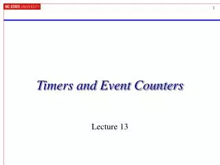
Timers and Event Counters These lecture notes created by Dr. Alex Dean, NCSU
In These Notes . . . • We learn the basics of the Timer/Counter peripheral • Called timers by Renesas • We examine how to set up the timers for different operation: • Event counting mode • Timer mode • Pulse Width Modulation (PWM) mode • One-shot timer mode • We also examine how to use a microcontroller in the timer mode
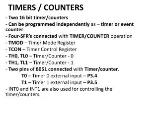
Reload Value Presettable Binary Counter Current Count Timer/Counter Introduction Events • Common peripheral for microcontrollers • Based on presettable binary counter, enhanced with configurability • Count value can be read and written by MCU • Count direction can often be set to up or down • Counter’s clock source can be selected • Counter mode: count pulses which indicate events (e.g. odometer pulses) • Timer mode: clock source is periodic, so counter value is proportional to elapsed time (e.g. stopwatch) • Counter’s overflow/underflow action can be selected • Generate interrupt • Reload counter with special value and continue counting • Toggle hardware output signal • Stop! Reload or ÷2 or RS PWM Clock Interrupt
Timer A Block Diagram • Each timer has one input, which is selectable from several different sources.
High-Level Timer A Block Diagram • Timer A devices will be the most frequently used • Flexible – can be cascaded to create larger timers (i.e. 32 bits long)
Timer A Mode Register • To use the timer, you must set up how you wish to use it (i.e. via TA0MR). After that, the mode register has different settings depending on bits 1 and 0.
Count Start Register • Once the timer has been loaded with a value, start it counting.
Timer Modes • We examine how to set up the timers for different operation: • Event counting mode • Timer mode • Pulse Width Modulation (PWM) mode • One-shot timer mode
Counter Mode • Count pulses representing events • Odometer example • Measure total distance your car has traveled • Events are wheel rotations, measured with magnetic sensors (dirt-proof!) • Distance travelled = counter value * 100.53” • Assume 16” tire radius. Tire circumference = 2pr = 100.53” • Will limited range of 16 bit counter be a problem? • 100.53” * (216-1) = 1247.78 miles • Yes. So need to extend range in software. • Enable overflow interrupt for the timer • Create an ISR to count overflows
Up/Down Flag • The default is that the timer will count down.
Trigger Select Register • You can set the trigger pulse of Timers A1 to A4
Example – Setting-up Event Mode #define TIME_CONFIG 0x01 /* 00000001 val to load into timer mode reg ||||||||_ TMOD0,TMOD1: EVENT COUNTR MODE ||||||____ MR0: NO PULSE OUTPUT |||||_____ MR1: COUNT FALLING EDGES ||||_______MR2: USE UP/DOWN FLAG |||_______ MR3: = 0 IN EVENT COUNTER MODE ||________ TCK0: RELOAD TYPE |__________TCK1: BIT NOT USED */ #define CNTR_IPL 0x03 // TA2 priority interrupt level void mcu_init() { … // Existing mcu_init() code ta2 = 100; //e.g for an automated packaging line, 100 items per case // the following procedure for writing an Interrupt Priority Level follows // that as described in the M16C data sheets under 'Interrupts' _asm (" fclr i") ; // turn off interrupts before modifying IPL ta2ic |= CNTR_IPL; // use read-modify-write instruction to write IPL ta2mr = TIME_CONFIG; _asm (" fset i"); ta2s = 1; //start counting }
Example – Using Event Mode #pragma INTERRUPT /B TimerA2Int void TimerA2Int(void) { int delaycntr; delaycntr = 0; count++; // e.g for an automated packaging line, cnts # of cases RED_LED = 1; while( delaycntr <0xffff) //software delay for flashing LED delaycntr++; RED_LED = 0; } // initializes variables and LED port. Then does nothing but // wait for TA2 interrupts. void main (void) { int temp; count = 0; mcu_init(); while (1); }
Timer Modes • We examine how to set up the timers for different operation: • Event counting mode • Timer mode • Pulse Width Modulation (PWM) mode • One-shot timer mode
Timer Mode – Measure Elapsed Time • Use a fixed-frequency signal fbase as a time-base • To measure elapsed time – automatically instead of measuring twiddle (debug) bits on an oscilloscope • Clear the timer (or read its value and subtract it out later) • Let time go by… • Read timer value (possibly subtract out start time) • Example void Compute_Cosine(float angle){ unsigned t_start, t_stop, t_cosine; t_start = timer_current_count; compute, calculate, approximate, interpolate, complete. t_stop = timer_current_count; t_cosine = t_stop – t_start; } • Gate function • Can use external signal (applied to TAiIN) to enable/disable counting • Can select counting during either high or low portion • Use MR1 and MR2 to configure • Convenient way to measure duty cycle WARNING:THIS CODE WILL NOT COMPILE
Timer Mode Demonstration • Use Timer A0 to generate an interrupt every 5 ms based on the 24 MHz system clock • In the TA0 ISR • Update a millisecond counter • Every 1000 ms • Update a second counter • Toggle the green LED • In the main code thread • Display current milliseconds, seconds values on LCD
Example – Setting Up Timer Mode #define TIME_CONFIG 0x40 /* 01000000 value to load into timer mode register ||||||||_ TMOD0,TMOD1: TIMER MODE SELECTED ||||||____ MR0: NO PULSE OUTPUT |||||_____ MR1,MR2: GATE FUNCTION NOT SELECTED |||_______ MR3: SET TO 0 IN TIMER MODE ||________ TCK0,TCK1: F DIVIDED BY 8 SELECTED */ #define CNTR_IPL 0x03 // TA0 priority interrupt level void mcu_init() { … // existing code from mcu_init() ta0 = 15000; // 24meg system clock, /8, *15000 counts-> 5msec interrupts. // the following procedure for writing an Interrupt Priority Level follows // that as described in the M16C data sheets under 'Interrupts' // Note: ta0ic is the interrupt control register, memory location x0055 _asm (" fclr i") ; //turn off interrupts before modifying IPL ta0ic |= CNTR_IPL; // use read-modify-write instruction to write IPL ta0mr = TIME_CONFIG; _asm (" fset i"); ta0s = 1; //start counting }
Example – Using Timer Mode #include "qsk_bsp.h" // include QSK board support package #include "stdio.h" // include support for sprintf volatile unsigned int msec_ctr; // Global millisecond counter volatile unsigned int sec_ctr; // Global second counter #pragma INTERRUPT /B TimerA0Int void TimerA0Int(void) { msec_ctr += 5; // timer interrupts every 5 ms if (msec_ctr > 1000) { // reached 1 second? GRN_LED ^= 1; // toggle LED sec_ctr++; // another second has gone by msec_ctr = 0; // reset ms counter } } void main(void) { char buf[9]; mcu_init(); // Initialize MCU InitDisplay(); DisplayString(LCD_LINE1, "Timers"); msec_ctr = 0; sec_ctr = 0; while (1) { //LED flashing is interrupt driven sprintf(buf, "%5d ms", msec_ctr); DisplayString(LCD_LINE1, buf); sprintf(buf, "%5d s", sec_ctr); DisplayString(LCD_LINE2, buf); } }
WARNING:BUGS LURKING IN CODE NEXT 20 MILES Extending Time Range in Software • Note: An n-bit counter will overflow every 2n/fbase seconds • 16-bit timer and 1 MHz clock ► 65.535 ms range • Need a variable to count overflows • Using unsigned int, can count 216-1overflows ► 232-1ticks • Time range: 232-1ticks at 1 MHz ► 4,294,967.295 ms ≈ 1.193 h unsigned int overflow_count=0; • Need an ISR which runs on overflow #pragma INTERRUPT timer_isr void timer_isr(void) { overflow_count++; } • Configure timer to continue counting upon overflow, don’t need reload with a special value • Need a function to merge overflow and timer information unsigned long get_ticks(void) return ((unsigned long) overflow_count << 16) + (unsigned long) ta3; } • Warning: this code will intermittently return an incorrect tick count! Shared Data Problem
Example – Timer & Event Mode • The maximum amount of time one can count using two timers is: • Cascade Timer A0 to Timer A1 • Use the 1/32 clock (bits 7 and 6 of TA0MR set to ’10’) • Set both timer values to xFFFF • Timer A1 output generates an interrupt • This would create a timer event which would interrupt the CPU every 6871 seconds (almost 2 hours!)
What Registers Need to be Set? /*Timer A0 mode register settings b7 b6 b5 b4 b3 b2 b1 b0 | | | | | | | |____ TA0D0 => 0 - 00 => timer mode | | | | | | |_______ TA0D1 => 0; | | | | | |__________ MR0 => 0 - TA0out is not used | | | | |_____________ MR1 => 0 - TA0in is not used | | | |________________ MR2 => 0; | | |___________________ MR3 => 0 - must be 0 in timer mode | |______________________ TCK0 => 0; |_________________________ TCK1 => 1 - TCK[10] => 00 is f1 or f2 => 01 is f8 => 10 is f32 => 11 is fc32 */ TA0MR = x80; // Timer A0 in timer mode with f32 clock /************************************************************************** - Timer A1 mode register settings b7 b6 b5 b4 b3 b2 b1 b0 | | | | | | | |____ TA1D0 => 1 - 01 => event counter mode | | | | | | |_______ TA1D1 => 0; | | | | | |__________ MR0 => 0 - TA1out is not used | | | | |_____________ MR1 => 0 - TA1in pin not used | | | |________________ MR2 => 0; - Up/Down flag used | | |___________________ MR3 => 0 - must be 0 in event counter mode | |______________________ TCK0 => 0; - reload type counter |_________________________ TCK1 => 0; - Invalid for regular counting*/ TA1MR = x01; // Timer A1 in event counter mode with reload enable
What Registers Need to be Set? /*Value to initialize TA0 and TA1 to each time at initialization and each time overflow occurs TAi/(XTAL * fx) = Z ms - where TAi is initialization value, XTAL is the clock frequency (20MHz) fx is the clock multiplier (1,1/8,1/32) Z is the miliseconds between overflows xFFFF = 65536 65536/(20,000,000 * 1/32) = 104.8576 milliseconds TA0 overflows every 104.8576 ms, TA1 counts the overflows up to 65536, then overflows every 6871.9 seconds (almost 2 hours) */ TA0 = xFFFF // value loaded into TA0 data register TA1 = xFFFF // value loaded into TA1 data register /****************************************************************** Count Start Flag -> b0 = 1 - start TA0 counting b1 = 1 - start TA1 counting b2-b7 - not applicable*/ TABSR = x03 // start Timers A0 and A1 counting
What Registers Need to be Set? Timer Up/Down Function Register -> b0 = 0 - TA0 counting down b1 = 0 - TA1 counting down b2-b7 - not applicable*/ UDF = x00; // UDF[10] => 00 makes Timers A0 and A1 count down /******************************************************************* - Timer Trigger Select Register b7 b6 b5 b4 b3 b2 b1 b0 | |____ TA1TGL => 0 - TA0 overflow select |_______ TA1TGH => 1; */ TGRSR = x02; // TA0 overflow is selected as trigger /********************************************************************* Set TA1 priority level interrupt; */ TA1IC = x03; // set TA1 priority level interrupt
Timer Modes • We examine how to set up the timers for different operation: • Event counting mode • Timer mode • Pulse Width Modulation (PWM) mode • One-shot timer mode
Pulse-Width Modulation • Often need to generate an analog value: motor speed, servo motor position, incandescent light dimmer, adj. switch-mode power supply • Analog circuits have some disadvantage • Generating the voltage accurately – circuits drift with temperature and time • Analog power amplifiers are inefficient (P = E*I) • Analog signals are much more sensitive to noise than digital signals • PWM provides a digital encoding of an analog value • Now circuits are digital: more efficient, less sensitive to noise, temperature, aging effects • PWM signal characteristics • Modulation frequency – how many pulses occur per second (fixed) • Period – 1/(modulation frequency) • On-time – amount of time that each pulse is on (asserted) • Duty-cycle – on-time/period • Adjust on-time (hence duty cycle) to create encoded analog value
Pulse-Width Modulation • We rely on low-pass filtering to “decode” (convert) this high-frequency PWM signal to an analog DC value • Variable speed motor control: Motor has inertia (will coast if power is turned off) • Incandescent Lamp Dimmer: Human eye has persistence of vision (retina averages signals above 30 Hz), and filament takes time to cool down and stop emitting visible light • Adjustable switch-mode power supply: Rely on inductor and capacitor to maintain current and voltage when not drawing current from battery • Many Timer/Counter peripherals can also generate PWM signal • For example • Count up • Set PWM output when counter value reaches 0 • Reset PWM output when counter value reaches n • When counter reaches 11.111, overflow and continue counting • Read Michael Barr’s Embedded Systems Programming article “Pulse Width Modulation” for more PWM information
Timer Modes • We examine how to set up the timers for different operation: • Event counting mode • Timer mode • Pulse Width Modulation (PWM) mode • One-shot timer mode
One-Shot Timer Mode • Set up timer to generate a time delay • Preload timer with a 16-bit value • Timer counts down to zero, clocked by f1, f2, f8, f32 or fC32 • Starting the timer • Set TAiS (start) bit for timer i • Select hardware or software trigger with MR2 bit in TAi Mode register • Software trigger: start by setting bit TAiOS (one-shot start) • Hardware trigger: start with trigger pulse selected by TRGSR • External input pulse on TAiIN (Select polarity with MR1 bit in TAi Mode register) • Output from one of three other timers • When timer reaches 0 • Counter reloads self with value from reload register and then stops • Counter can generate interrupt (if enabled) • Pulse output • Can enable on TAiOUT • 1 when counting, 0 when stopped • Use cases • “Interrupt me after 30 ms” • “Generate a 100 us pulse for every rising edge on TA3IN” • “Interrupt me 50 ms after TA3IN falls”
Example Code void Set_TA0_Delay(unsigned long ticks) { if (ticks > 0xffff) ticks = 0xffff; ta0 = ticks; ta0s = 1; //enable counting // start one-shot counting now ta0os = 1; } // also need an ISR for TA0! void main(void) { // Initialize MCU mcu_init(); timer_init(); Set_TA0_Delay(100); while (1) { /* interrupt will happen after 100 ticks */ }; } void timer_init(void) { // one shot timer mode // Turn off ints before // modifying IPL _asm (" fclr i") ; ta0ic |= CNTR_IPL; // one-shot timer mode tmod0_ta0mr = 0; tmod1_ta0mr = 1; // no output pulse mr0_ta0mr = 0; // trigger is software -- TA0OS bit mr2_ta0mr = 0; // must be 0 mr3_ta0mr = 0; // select f32 tck0_ta0mr = 0; tck1_ta0mr = 1; // enable interrupts _asm (" fset i"); }