Download
1 / 13
130 likes | 132 Views
Learn practical tips and strategies for object modeling, including explicit scheduling of meetings for object identification, differentiation between entity, boundary, and control objects, finding associations and their multiplicities, and more. This lecture also explores the role of software engineers in system analysis and the construction of the object and dynamic models.

E N D
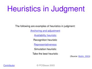
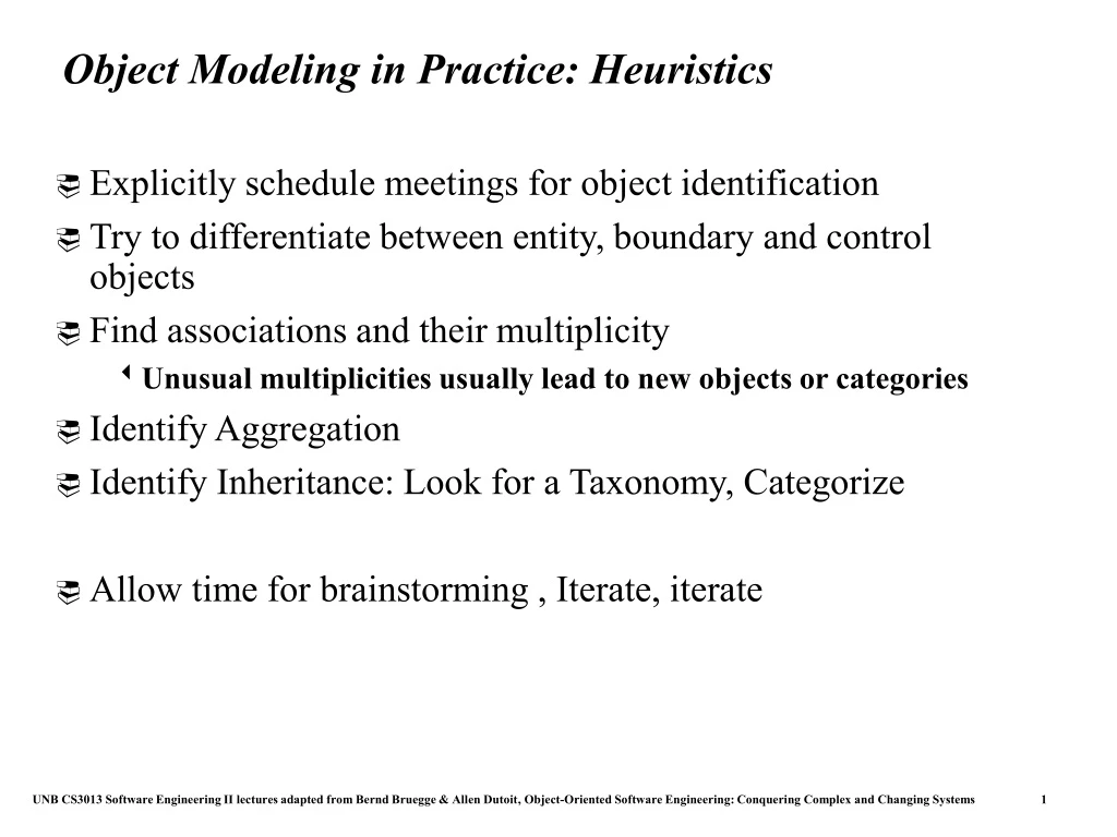
Object Modeling in Practice: Heuristics • Explicitly schedule meetings for object identification • Try to differentiate between entity, boundary and control objects • Find associations and their multiplicity • Unusual multiplicities usually lead to new objects or categories • Identify Aggregation • Identify Inheritance: Look for a Taxonomy, Categorize • Allow time for brainstorming , Iterate, iterate
What is a Software Engineer? • From the point of view of phenomenology, Software Engineers are dialectic monistic idealists: • Idealists: • They accept that ideas (called requirements or “customer’s wishlist”) are different from reality. • They are not realists: • The reality might not yet exist (“Vaporware is always possible ”) • They are monistic: • They are optimistic that their ideas can describe reality (“das Ding an sich”). • Dialectic: • They do this in a dialogue with the customer
Summary In this lecture, we reviewed the construction of the object model from use case model. In particular, we described: • Identification of objects • Refinement of objects with attributes and operations • Generalization of concrete classes • Identification of associations • Reduction of multiplicity using qualification. In the next lecture, we describe the construction of the dynamic model from the use case and object models.
The Building Access Control System – Part I • Design of a building access control system [ Wrox Press web site (http://www.wrox.com), also http://faculty.ed.umuc.edu/~cklein] • The space to be protected is divided over 4 floors of a building with a total area of about 5000M2. The building itself is divided into five areas: two research wings, an experimental wing, an administration wing, and a central section containing classrooms and the two lecture halls. • The site accommodates about 500 people every day: mostly students,. but also teachers, researchers, administrative and technical staff, as well as numerous visitors. • After various items of property started disappearing, it was decided to restrict access to some of the rooms using doors with automaticlocking. The opening of each door is controlled by a badge reader, located nearby. • The badges that allow the opening of these doors are only given to the people that need to access restricted areas in order to perform theirduties. Access rights are distributed among groups of people and groups of doors. Each person and each door must always belong to a group, even if they are the only member of that group.
The Building Access Control System – Part II • A group of doors may consist of doors distributed throughout the building, but from the point of view of controlling access, only the concept of a group of doors is important - routes and movement are not controlled. However, a given door cannot be a member of more than one group of doors. A given person, on the other hand, may be 'a member of several groups, so that his or her access rights correspond to the combined rights of each of the groups he or she belongs to. • Access rights are established by describing, for each group of people, the various groups of doors that are accessible and under what time constraints. These rights are contained in a yearly calendar that describes the schedule a week at a time. Given that there will be a small variation of rights over time, a calendar may be initialized using 'typical' weeks that describe a fixed configuration of rights. The supervisor may create as many 'typical' weeks as she wishes, and any subsequent changes made will automatically be propagated to all the calendars using them. On the other hand, changes made to a calendar directly - to take vacation days into consideration, for example - are not affected by the modification of a 'typical' week.
The Building Access Control System – Part III • The following table [not shown] represents a typical week. The grayed areas correspond to time periods during which access is not authorized. [The table shows access allowed from 7 a.m. through 10 p.m. each weekday]. • The access control system must operate as autonomously as possible, although a supervisor is responsible for the initial configuration and the updating of the various pieces of information that define the groups of people and doors. A guard has a control screen, and is informed of any unsuccessful entry attempts. Alarms are transmitted with a slight delay: information update on the control screen is performed every minute. • The user interface must help the users to specify their requestscorrectly. Legal requests and input values are systematically read from lists that define the domain of correct values.
Outline • Dynamic modeling • Sequence diagrams • State diagrams • Using dynamic modeling for the design of user interfaces • Analysis example • Requirements analysis document template
Example of use case format Use case name ReportEmergency Entry condition 1. The FieldOfficer activates the “Report Emergency” function of her terminal. Flow of events 2. FRIEND responds by presenting a form to the officer... 3. The FieldOfficer fills the form.... 4. The Dispatcher reviews the information submitted by the FieldOfficer ... Exit condition 5. The FieldOfficer receives the acknowledgment and the selected response.
How do you find classes? • From previous lectures • Application domain analysis: Talk to client to identify abstractions • Apply general world knowledge and intuition • Scenarios • Natural language formulation of a concrete usage of the system • Use Cases • Natural language formulation of the functions of the system • Textual analysis of problem statement (Abbot) • From this lecture • Dynamic model • Events: Candiates for operations to be offered by classes • Sequence diagrams as sources for objects • From future lectures • Design Patterns
Dynamic Modeling with UML • Diagrams for dynamic modeling • Interaction diagrams describe the dynamic behavior between objects • Statecharts describe the dynamic behavior of a single object • Interaction diagrams • Sequence Diagram: • Dynamic behavior of a set of objects arranged in time sequence. • Good for real-time specifications and complex scenarios • Collaboration Diagram : • Shows the relationship among objects. Does not show time • State Charts: • A state machine that describes the response of an object of a given class to the receipt of outside stimuli (Events). • Activity Diagram: • Special type of statechart where all states are action states
Dynamic Modeling • Definition of dynamic model: • A collection of multiple state chart diagrams, one state chart diagram for each class with important dynamic behavior. • Purpose: • Detect and supply methods for the object model • How do we do this? • Start with use case or scenario • Model interaction between objects => sequence diagram • Model dynamic behavior of single objects => statechart diagram