Download
1 / 15
210 likes | 493 Views
MARADIN MEMS SCANNING MIRROR Applications and Synchronization Notes . Sharon Hornstein, PhD. Optical Engineering Conf. February 26 th , 2014. Outline. About Maradin MEMS Mirror - motion definition Problem definition:

E N D
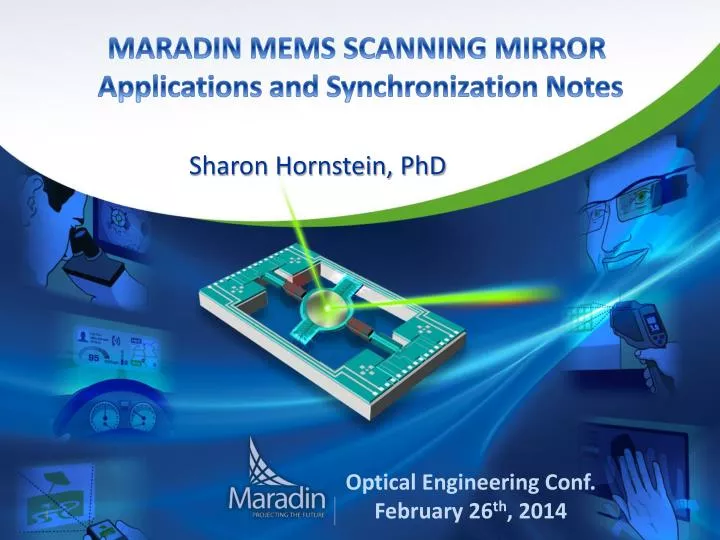
MARADIN MEMS SCANNING MIRROR Applications and Synchronization Notes Sharon Hornstein, PhD Optical Engineering Conf. February 26th, 2014
Outline • About Maradin • MEMS Mirror - motion definition • Problem definition: Why are image corrections needed when a scanning mirror is used for projection? • The algorithm for image correction, using laser modulation. • Summary
About Maradin • Fabless MEMS company (Founded in 2007) • Develop innovative MEMS Scanning Mirror solutions for laser projection and laser scanning applications • Experienced and committed Team, in MEMS, Semiconductors, and System • Electronics, Mechanics, Dynamics, Control, Material Science, Semi-conductor’s processing • Privately held, backed by solid investors and industry veterans
The Core of Laser Steering Systems Laser Diodes + Optics Maradin 2D MEMS Scanning Mirror Maradin Chipset Laser Driver Maradin Laser Timing Algorithm Maradin MEMS Drive & Control Video Data
Markets and Applications Pico Projectors Automotive HUD Medical Eyewear Displays Large Displays More to emerge… Industrial Gesture Sensing
2D MEMS Mirror • Horizontal Axis: • Electro-static actuator built into Silicon • Operation at resonance (~10KHz) • Capacitive sensing and resonance lock control • Vertical Axis: • Hybrid Electro-magnetic actuator (“DC” motor) • Step function scanning • Modulated capacitance sensing and position control
MEMS Mirror - motion definition • Horizontal Axis – Sinusoidal Motion (~10KHz]) • Vertical Axis – Saw Tooth Pattern (60Hz]) Reference signal Sensor measurement
Projection – System Sketch Spherical (3D) Projected Surface Planar (2D) image Mirror position
Projection – 3D Surface and Projections Front View X-Y Plane Side View X-Z Plane Optical Distortions
Y Problem Definition X • The mirror is resonating in a sinusoidal profile. Its non-constant velocity implies a non-uniform distribution of pixels along the lines. Differences in mirror velocity create non-uniform brightness along the lines Y direction X direction • The scanning mirror creates a 3D surface. The image is created by intersection of light onto a 2D plane. • Pincushion distortion (e.g. bowed boundaries) due to geometry.
Solution Method – Laser Modulation • Avoid edge-effects – only 70% of the mirror’s period is used for projection 70% (T/2)
Algorithm – Eliminate Distortions • Eliminate geometrical (Pincushion, Barrel) distortionsby defining a different initial projection time for each row
Algorithm – Uniform Distribution of Pixels 2 3 4 1 6 9 14 5 10 11 12 3 4 13 1 8 2 7 15 19 21 10 8 14 5 12 17 Result: uniform distribution
Results • “Target Resolution“: • Linearly distributed pixels along the x axis • Vertical lines are one-pixel width • Fine Forward\backward alignment • Diagonal lines are sharp (not bowed)
Thank you! Maradin Ltd. P.O. Box 56YokneamIndustrial Park, South Yokneam20692,Israel Tel. +972 (4) 627 3653 | Fax. +972 (4) 959 0327 www.maradin.co.il