Download
1 / 7
70 likes | 189 Views
Single Board Controller Comments. Roger Smith Caltech 2013-05-13. Single Board Controller. Motivated by the need for high ADC clock rates Clocks exceeding 140 MHz (or more) FPGA adjacent to ADC is necessary Eliminates backplane complexity

E N D
Single Board Controller Comments Roger Smith Caltech 2013-05-13
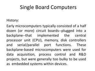
Single Board Controller • Motivated by the need for high ADC clock rates • Clocks exceeding 140 MHz (or more) • FPGA adjacent to ADC is necessary • Eliminates backplane complexity • High speed signals no longer travel along backplane • Advantage of a single low impedance analog ground plane • Board performance not affected when placed on extenders • Final package has A/C power in and USB out
Single Board Challenges/Questions • Will everything fit on a single board? • Would like to use standard size (eg. 6U VME board) • Custom size board not out of the question • Custom sizes require a custom enclosure • Power requirements • Associated power board with single board controller • Do power requirements allow for a compact power supply board? • Other questions/challenges?
USB over fiber AC power Electronics box Front panels with ejectors • We are contemplating a single board CCD controller to operate both science and guide CCDs, plugging this directly into a slightly extended vacuum interface board. • Plug-in power supply between board and dewar within same enclosure. • Remove side panel to gain access to test points on controller board. • Board dimensions are TBD. • Box mounts to flat faces of dewar. Its ok to have to remove boards to access bolts. • Cooling by conduction to dewar. 8 ch CCD controller Power modules 283 mm
Electronics box mount PCB dimensions are yet TBD…. Options to consider: • Eurocard 6U = 230mm wide * 160mm deep like VME. • Extended 3U = 100mm wide * 230mm deep like Leach controller. • This provides less lateral overhang. • Is this enough board area? • Do Vicor power modules fit in this space? Plug in Power Controller 278 mm
Electronics box – faceted option If we go with two 4ch single board controllers, there is the option of placing the boards side by side along the circumference. (Leach controller boards are 100mm wide * 230mm deep) Advantages: • Easier trace routing through VIB • Direct heat sinking to dewar for all boards. • Very compact. Disadvantages ? • Unusual enclosure topology? Is this really a problem? 4ch Controller 92 mm 114 mm Plug in Power 4ch Controller
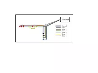
Ground plane topology Card ejectors Front Panel Four ground planes join here: • Digital • Analog supply return • Analog reference (not shown) • Clock (high current analog) USB Digital Sequencer Dense FPGA TBD whether FPGAs are same device or separate. DCDSFast FPGA ADC ADC ADC ADC Clock DACs ADC buffers Clock Switches Bias DACs Clock Drivers Bias Drivers Power planes mimic grounds but need low impedance paths to connector Connector