Download
1 / 83
1.32k likes | 2.06k Views
Unified Modeling Language. Chapter5. Introduction. A model is an abstract representation of a system, constructed to understand the system prior to building or modifying it. The term system is used here in a broad sense to include any process or structure.

E N D
Unified Modeling Language Chapter5 Object Oriented Systems Development
Introduction • A model is an abstract representation of a system, constructed to understand the system prior to building or modifying it. • The term system is used here in a broad sense to include any process or structure. • For example, the organizational structure of a corporation, health services, computer software, instruction of any sort (including computers), the national economy, and so forth all would be termed systems. Object Oriented Systems Development
Introduction • A model is simplified because reality is too complex or large and much of the complexity actually is irrelevant to the problem we are trying to describe or solve. • A model provides a means for conceptualization and communication of ideas in a precise and unambiguous form. Object Oriented Systems Development
Introduction • Most modeling techniques used for analysis and design involve graphic languages. • These graphic languages are sets of symbols. • The symbols are used according to certain rules of the methodology for communicating the complex relationships of information more clearly than descriptive text. Object Oriented Systems Development
Introduction • Objectory is built around several different models: • Use-case model. The use-case model defines the outside (actors) and inside (use case) of the system's behavior. • Domain object model. Objects of the "real" world are mapped into the domain object model. • Analysis object model. The analysis object model presents how the source code (i.e., the implementation) should be carried out and written. • Implementation model. The implementation model represents the implementation of the system. • Test model. The test model constitutes the test plans, specifications, and reports. Object Oriented Systems Development
STATIC AND DYNAMIC MODELS • A static model can be viewed as a snapshot of a system's parameters at rest or at a specific point in time. • Static models are needed to represent the structural or static aspect of a system. • For example, a customer could have more than one account or an order could be aggregated from one or more line items. Static models assume stability and an absence of change in data over time. • The unified modeling language class diagram is an example of a static model. Object Oriented Systems Development
STATIC AND DYNAMIC MODELS • A dynamic model, in contrast to a static model, can be viewed as a collection of procedures or behaviors that, taken together, reflect the behavior of a system over time. • Dynamic relationships show how the business objects interact to perform tasks. • For example, an order interacts with inventory to determine product availability. Object Oriented Systems Development
WHY MODELING? • Building a model for a software system prior to its construction is as essential as having a blueprint for building a large building. • Good models are essential for communication among project teams. • As the complexity of systems increases, so does the importance of good modeling techniques. • Many other factors add to a project's success, but having a rigorous modeling language is essential. Object Oriented Systems Development
WHY MODELING? • A modeling language must include: • Model elements—fundamental modeling concepts and semantics. • Notation—visual rendering of model elements. • Guidelines—expression of usage within the trade. Object Oriented Systems Development
WHY MODELING? • The use of visual notation to represent or model a problem can provide us several benefits relating to clarity, familiarity, maintenance, and simplification. • Clarity. • We are much better at picking out errors and omissions from a graphical or visual representation than from listings of code or tables of numbers. • We very easily can understand the system being modeled because visual examination of the whole is possible. Object Oriented Systems Development
WHY MODELING? • Familiarity. • The representation form for the model may turn out to be similar to the way in which the information actually is represented and used by the employees currently working in the problem domain • Simplification. • Use of a higher level representation generally results in the use of fewer but more general constructs, contributing to simplicity and conceptual understanding. Object Oriented Systems Development
WHY MODELING? • Maintenance. • Visual notation can improve the maintainability of a system. • The visual identification of locations to be changed and the visual confirmation of those changes will reduce errors. • Thus, you can make changes faster, and fewer errors are likely to be introduced in the process of making those changes. Object Oriented Systems Development
Advantages of modeling: • Turban cites the following advantages of modeling: • Models make it easier to express complex ideas. For example, an architect builds a model to communicate ideas more easily to clients. • The main reason for modeling is the reduction of complexity. Models reduce complexity by separating those aspects that are unimportant from those that are important. Therefore, it makes complex situations easier to understand. Object Oriented Systems Development
Advantages of modeling: • Models enhance and reinforce learning and training. • The cost of the modeling analysis is much lower than the cost of similar experimentation conducted with a real system. • Manipulation of the model (changing variables) is much easier than manipulating a real system. Object Oriented Systems Development
Summary of Modeling • To summarize, here are a few key ideas regarding modeling: • A model is rarely correct on the first try. • Always seek the advice and criticism of others. You can improve a model by reconciling different perspectives. • Avoid excess model revisions, as they can distort the essence of your model. Let simplicity and elegance guide you through the process. Object Oriented Systems Development
INTRODUCTION TO THE UNIFIED MODELING LANGUAGE • The unified modeling language is a language for specifying, constructing, visualizing, and documenting the software system and its components. • The UML is a graphical language with sets of rules and semantics. • The rules and semantics of a model are expressed in English, in a form known as object constraint language (OCL). • OCL is a specification language that uses simple logic for specifying the properties of a system. Object Oriented Systems Development
INTRODUCTION TO THE UNIFIED MODELING LANGUAGE • The UML is not intended to be a visual programming language however, the UML does have a tight mapping to a family of object-oriented languages, so that you can get the best of both worlds. • The goals of the unification efforts were to keep it simple; to cast away elements of existing Booch, OMT, and OOSE methods that did not work in practice; to add elements from other methods that were more effective; and to invent new methods only when an existing solution was unavailable. Object Oriented Systems Development
GOALS IN THE DESIGN OF UML • The primary goals in the design of the UML were as follows: • Provide users a ready-to-use, expressive visual modeling language so they can develop and exchange meaningful models. • Provide extensibility and specialization mechanisms to extend the core concepts. • Be independent of particular programming languages and development processes. Object Oriented Systems Development
GOALS IN THE DESIGN OF UML • Provide a formal basis for understanding the modeling language. • Encourage the growth of the OO tools market. • Support higher-level development concepts. • Integrate best practices and methodologies. Object Oriented Systems Development
UML DIAGRAMS • The UML defines nine graphical diagrams: • Class diagram (static) • Use-case diagram • Behavior diagram (dynamic): • Interaction diagram: • Sequence diagram • Collaboration diagram • State chart diagram • Activity diagram • Implementation diagram: • Component diagram • Deployment diagram Object Oriented Systems Development
UML CLASS DIAGRAM • The UML class diagram, also referred to as object modeling, is the main static analysis diagram. • These diagrams show the static structure of the model. • A class diagram is a collection of static modeling elements, such as classes and their relationships, connected as a graph to each other and to their contents; for example, the things that exist (such as classes), their internal structures, and their relationships to other classes. Object Oriented Systems Development
UML CLASS DIAGRAM • Class diagrams do not show temporal information, which is required in dynamic modeling. • Object modeling is the process by which the logical objects in the real world (problem space) are represented (mapped) by the actual objects in the program (logical or a mini world). • This visual representation of the objects, their relationships, and their structures is for ease of understanding. Object Oriented Systems Development
Class Notation: Static Structure • A class is drawn as a rectangle with three components separated by horizontal lines. • The top name compartment holds the class name, other general properties of the class, such as attributes, are in the middle compartment, and the bottom compartment holds a list of operations. Object Oriented Systems Development
Class Notation: Static Structure • Either or both the attribute and operation compartments may be suppressed. • The class name and other properties should be displayed in up to three sections. • A stylistic convention of UML is to use an italic font for abstract classes and a normal (roman) font for concrete classes. Object Oriented Systems Development
Object Diagram • A static object diagram is an instance of a class diagram. • It shows a snapshot of the detailed state of the system at a point in time. • Notation is the same for an object diagram and a class diagram. • Class diagrams can contain objects, so a class diagram with objects and no classes is an object diagram. Object Oriented Systems Development
Class Interface Notation • Class interface notation is used to describe the externally visible behavior of a class; for example, an operation with public visibility. • The UML notation for an interface is a small circle with the name of the interface connected to the class. • A class that requires the operations in the interface may be attached to the circle by a dashed arrow. • The dependent class is not required to actually use all of the operations. Object Oriented Systems Development
Class Interface Notation • For example, a Person object may need to interact with the BankAccount object to get the Balance; Object Oriented Systems Development
Binary Association Notation • A binary association is drawn as a solid path connecting two classes, or both ends may be connected to the same class. • An association may have an association name. • Furthermore, the association name may have an optional black triangle in it, the point of the triangle indicating the direction in which to read the name. • The end of an association, where it connects to a class, is called the association role Object Oriented Systems Development
Binary Association Notation Object Oriented Systems Development
Association Role • A simple association—the technical term for it is binary association—is drawn as a solid line connecting two class symbols. • The end of an association, where it connects to a class, shows the association role. • The role is part of the association, not part of the class. • Each association has two or more roles to which it is connected. • In Figure 5-3, the association worksFor connects two roles, employee and employer. Object Oriented Systems Development
Association Role • The UML uses the term association navigation or navigability to specify a role affiliated with each end of an association relationship. • An arrow may be attached to the end of the path to indicate that navigation is supported in the direction of the class pointed to. • An arrow may be attached to neither, one, or both ends of the path. Object Oriented Systems Development
Qualifier • A qualifier is an association attribute. For example, a person object may be associated to a Bank object. • An attribute of this association is the account#. • The account# is the qualifier of this association (see Figure -5-5). Object Oriented Systems Development
Qualifier Object Oriented Systems Development
Qualifier • A qualifier is shown as a small rectangle attached to the end of an association path, between the final path segment and the symbol of the class to which it connects. • The qualifier rectangle is part of the association path, not part of the class. • The qualifier rectangle usually is smaller than the attached class rectangle Object Oriented Systems Development
Multiplicity • Multiplicity specifies the range of allowable associated classes. • It is given for roles within associations, parts within and other purposes. • A multiplicity specification is shown as a text string comprising a period-separated sequence of integrated intervals, where an interval represents a range of integers in this format (see Figure 5-5): • lower bound .. upper bound. Object Oriented Systems Development
Multiplicity • The terms lower bound and upper bound are integer values, specifying the range of integers including the lower bound to the upper bound. • The star character (*) may be used for the upper bound, denoting an unlimited upper bound. • If a single integer value is specified, then the integer range contains the single values. For example, • 0..1 Object Oriented Systems Development
OR Association • An OR association indicates a situation in which only one of several potential associations may be instantiated at one time for any single object. • This is shown as a dashed line connecting two or more associations, all of which must have a class in common, with the constraint string {or} labeling the dashed line. Object Oriented Systems Development
OR Association Object Oriented Systems Development
Association Class • An association class is an association that also has class properties. • An association class is shown as a class symbol attached by a dashed line to an association path. • The name in the class symbol and the name string attached to the association path are the same. Object Oriented Systems Development
Association Class Object Oriented Systems Development
Association Class • The name can be shown on the path or the class symbol or both. • If an association class has attributes but no operations or other associations, then the name may be displayed on the association path and omitted from the association class to emphasize its "association nature." Object Oriented Systems Development
N-Ary Association • An n-ary association is an association among more than two classes. • Since n-ary association is more difficult to understand, it is better to convert an n-ary association to binary association. • An n-ary association is shown as a large diamond with a path from the diamond to each participant class. Object Oriented Systems Development
N-Ary Association • The name of the association (if any) is shown near the diamond. • The role attachment may appear on each path as with a binary association. • Multiplicity may be indicated; however, qualifiers and aggregation are not permitted. Object Oriented Systems Development
N-Ary Association • .An association class symbol may be attached to the diamond by a dashed line, indicating an n-ary association that has attributes, operation, or associations. Object Oriented Systems Development
N-Ary Association Object Oriented Systems Development
Aggregation and Composition (a-part-of) • Aggregation is a form of association. • A hollow diamond is attached to the end of the path to indicate aggregation. • However, the diamond may not be attached to both ends of a line, and it need not be presented at all. Object Oriented Systems Development
Aggregation and Composition (a-part-of) • Composition, also known as the a-part-of, is a form of aggregation with strong ownership to represent the component of a complex object. • Composition also is referred to as a part-whole relationship. • The UML notation for composition is a solid diamond at the end of a path. Object Oriented Systems Development
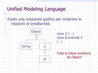
Generalization • Generalization is the relationship between a more general class and a more specific class. • Generalization is displayed as a directed line with a closed, hollow arrowhead at the superclass end. • Ellipses (…) indicate that the generalization is incomplete and more subclasses exist that are not shown. Object Oriented Systems Development
Generalization • If a text label is placed on the hollow triangle shared by several generalization paths to subclasses, the label applies to all of the paths. • In other words, all subclasses share the given properties. Object Oriented Systems Development
USE-CASE DIAGRAM • The use-case concept was introduced by Ivar Jacobson in the object-oriented software engineering (OOSE) method. • The functionality of a system is described in a number of different use cases, each of which represents a specific flow of events in the system. Object Oriented Systems Development