Download
1 / 24
290 likes | 675 Views
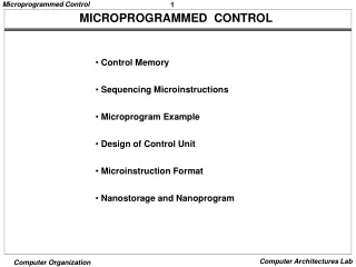
Chapter 17. Microprogrammed Control ( Cont. ). Lecture 12. Organization of Control Memory. Control Unit. Functioning of Control Unit. Inst address. Sequencing logic unit issues read command. Word specified in control address register is read into control buffer register.

E N D
Chapter 17. Microprogrammed Control (Cont.) Lecture 12
Functioning of Control Unit Inst address • Sequencing logic unit issues read command. • Word specified in control address register is read into control buffer register. • Control buffer register contents generate control signals and next address information. • Sequencing logic loads new address into control address register based on next address information from control buffer register and ALU flags. • All done during 1 clock cycle. For vertical mircoinst.
Next Address Decision • Depending on ALU flags and control buffer register • Get next microinstruction • Add 1 to control address register. • Jump to new routine based on jump microinstruction • Load address field of control buffer register into control address register. • Jump to machine instruction routine • Load control address register based on opcode in IR.
Advantages and Disadvantages of Microprogramming • Simplifies design of control unit • Cheaper. • Less error-prone. • Slower. • Dominant in CISC machines. • RISC processors use hardwired control due to their simpler instructions.
Tasks Done By Microprogrammed Control Unit • Microinstruction sequencing • Get next microinstruction from the control memory. • Microinstruction execution • Generate the control signals needed to execute the microinstruction. • Must consider both together.
Design Considerations • Size of microinstructions • Small small control memory cheap. • Address of next microinstruction • Generation time: short fast execution • Determined by instruction register • Once per cycle, after instruction is fetched • Next sequential address • Common in most designs • Branches • Both conditional and unconditional • One out of every 3 or 4 microinstructions.
Sequencing Techniques • Based on current microinstruction, condition flags, and contents of IR, control memory address must be generated. • Based on format of address information: • Two address fields. • Single address field. • Variable format.
Branch Control Logic: Two Address Fields Multiplexer transmits either the opcode or one of the addresses to CAR.
Branch Control Logic: Single Address Field Saves space. The address field often will not be used.
Branch Control Logic: Variable Format • One bit designates which format. • Format 1: bits are to activate control signals. Address = next sequential or derived from IR. • Format 2: some bits drive the branch logic, remaining for the address. Conditional or unconditional branch is specified. One extra clock cycle with every branch microinstruction.
Address Generation Techniques • Explicit • 2 address fields, single address field, and variable format. • Conditional branch instruction depends on: • ALU flags. • Opcode or addressing modes. • Parts of a selected register (e.g., sign bit). • Status bits within the control unit. • Implicit • Mapping: opcode is mapped into a microinstruction address. • Addition: add two portions of an address to form a complete address. • Residual control: address previously saved in temporary storage (subroutine call).
Microinstruction Execution • The microinstruction cycle is the basic event. • Each cycle is made up of two events: • Fetch • Determined by generation of microinstruction address. • Execute • Generate control signals. • Effect is to generate control signals. • Some control points internal to processor. • Rest go to external control bus or other interface.
Control Unit Organization • Sequencing logic • Inputs: ALU flags, clock, IR, CAR (for incrementing), and control buffer register (actual address or control bits). • Outputs: address of next microinstruction. • Control logic • Generates control signals as a function of some of the bits in the microinstruction.
How Microinstructions can be Encoded • K different internal and external control signals. • K bits dedicated • 2K possible combinations of control signals during any instruction cycle. • Not all are used • Two sources cannot be gated to same destination • Register cannot be source and destination. • Only one pattern presented to ALU at a time. • Only one pattern presented to external control bus at a time. • Require Q < 2K which can be encoded with log2Q < K bits. • Not done • As difficult to program as pure decoded scheme. • Requires complex slow control logic module. • Compromises • More bits than necessary used. • Some combinations that are physically allowable are not possible to encode.
A Taxonomy of Microinstructions • Vertical/horizontal • Relative width of microinstructions. • Vertical: 16-40 bits • Horizontal: 40-100 bits • Packed/unpacked • More packed bits a given # of bits contains more information. • Soft/hard microprogramming • Degree of closeness to control signals and hardware layout. • Direct/indirect encoding
Specific Encoding Techniques • Microinstruction organized as a set of fields. • Each field contains code. • Activates one or more control signals. • Organize format into independent fields • Field depicts set of actions (patterns of control signals). • Actions from different fields can occur simultaneously. • Alternative actions that can be specified by a field are mutually exclusive • Only one action specified for field could occur at a time.
Microinstruction EncodingDirect Encoding • Each field = code. Upon decoding, activates one or more control signals. • L-bit field contains one of 2L codes 2L control signal patterns. • Only one code can appear in a field at a time codes are mutually exclusive actions they do are mutually exclusive. • Functional encoding • Identify functions and designate fields by function type. • e.g., a field to identify which source is transferring data to the accumulator. • Resource encoding • View the machine as consisting of independent resources, devote one field for every one (I/O, memory, ALU).
Microinstruction EncodingIndirect Encoding • One field determines the interpretation of another field. • e.g., an ALU doing 8 arithmetic operations and 8 shift operations. A 1-bit field can be used to indicate arithmetic/shit, 3 bits can indicate the operation. • Two levels of decoding propagation delay.
Vertical Microinstruction – Example • Simple CPU with an accumulator, temp. register for ALU, PC. • First 3 bits: type of operation, next 3 bits: operation, last 2 bits: select a register.
Horizontal Microinstruction – Example • Encoding is still used (slightly). • Different functions appear in different fields.
Reading Material • Stallings, Chapter 17, pages 602-605, 607-622.