Download
1 / 35
350 likes | 475 Views
Ch. 30 Inductance. AP Physics. According to Faraday’s law, an emf is induced in a stationary circuit whenever the magnetic flux varies with time. If this flux variation is caused by a varying current in a second circuit, the induced emf can be expressed in terms of varying current, i .

E N D
Ch. 30 Inductance AP Physics
According to Faraday’s law, an emf is induced in a stationary circuit whenever the magnetic flux varies with time. If this flux variation is caused by a varying current in a second circuit, the induced emf can be expressed in terms of varying current, i. Mutual Inductance
A changing current in one circuit causes a changing magnetic flux and induced emf in a neighboring circuit that is proportional to the rate of change in current. The proportionality constant is called the mutual inductance. Mutual Inductance
As the current changes in the primary coil, the magnetic flux changes in the secondary coil which induces an emf in the secondary coil. Mutual Inductance
Mutual inductance of the coil is defined to be Mutual Inductance
If the coils are in a vacuum, then M21 depends on the geometry of the coils. If a magnetic material is present, then M21 depends on the properties of the magnetic material. • Note: We will assume that the flux is directly proportional to the current; that is, M21 = M12always!! Mutual Inductance
In symbols, • Therefore, • and Mutual Inductance
The negative sign show that the direction of the induced emf in each coil is opposite to the rate of change of current in the other coil. • The measurement unit for mutual inductance is: 1 Wb/A = 1 V-s/A = 1 Ω-s = 1 Henry (H) Mutual Inductance
A long solenoid with length l and cross-sectional area A and N1 turns of wire is surrounded by a coil of N2 turns. Find the mutual inductance. Tesla Coil
Suppose the length of the solenoid in the previous slide is 0.50 m, A = 10 sq. cm., N1 = 10 turns, and N2 = 1000, calculate the mutual inductance. Sample Problem #1
Suppose i1 = (2.0 A/s) t, at t = 3.0 s, what is the average magnetic flux through each turn of the solenoid caused the current in the larger coil of the Tesla coil. • What is the induced emf in the solenoid? Sample Problem #2
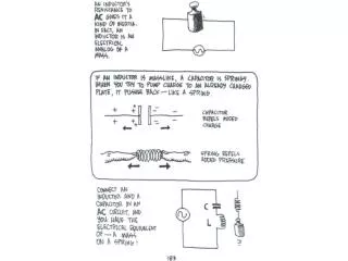
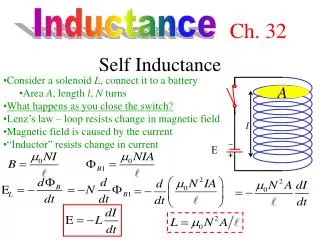
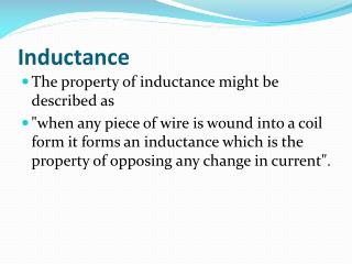
When a current is present in any circuit, the current sets up a magnetic field that links with the same circuit and changes when the current changes. Any circuit that carries a varying current has an induced emf in it resulting from the variation in its own magnetic field. Such an emf is called a self-induced emf. This is also called back emf. Self-Inductance
Consider a coil with N turns, carrying a current i. As a result of this current, a magnetic flux passes through each turn. Self-inductance is defined to be • From Faraday’s law, Self-Inductance
An inductor or choke is an electrical component of a circuit that is designed to have a particular inductance. • The schematic symbol is: • The cause of the induced emf and the field is the changing current in the inductor, and the emf always act to oppose this change according to Lenz’s law; that is, Inductor
Case 1. Current is increasing, > 0, VL > 0, ε < 0 i increasing • Case 2. Current is constant • Case 3. Current is decreasing How do the values change in cases 2 & 3?
Find the inductance of a uniformly wound solenoid having N turns and length l. Assume that l is much longer than the radius of the windings and that the core of the solenoid is air. Sample Problem #3
Calculate the inductance of an air-core solenoid containing 300 turns if the length of the solenoid is 25.0 cm and its cross-sectional area is 4.00 sq. cm. • Calculate the self-induced emf in the solenoid if the current through it is decreasing at the rate of 50.0 A/s. Sample Problem #4
Establishing a current within an inductor requires an input of energy, and an inductor carrying a current has energy stored in it. A changing current in an inductor causes an emf between their terminals. The source supplies the current must maintain a corresponding potential difference between its terminals. Magnetic Field Energy
Let the current at some time be i and its increasing rate of change is di/dt. Then VL = Ldi/dt and P = Vli = Lidi/dt. Since P = dU/dt, then dU/dt = Lidi/dt. • Therefore, • The total energy is • The energy in an inductor is stored in the magnetic field within the coil. Magnetic Field Energy
The energy stored in an inductor is 1.00 kWh. If the current is 2.00 A, what is the inductance? Sample Problem #5
The inductance of the inductor results ina back emf, an inductor in a circuit opposes changes in the current through that circuit. • If the battery voltage in the circuit increased so that the current rises, the inductor opposes this change, and the rise is not instantaneous. • If the battery voltage is decreased, the presences of the inductor results in a slow drop in the current rather than an immediate drop. • Thus, the inductor causes the circuit to be ‘sluggish’ as it reacts to changes in the current. RL Circuits
A switch controls the current in a circuit that has a large inductance. Is a spark more likely to be produced at the switch when the switch is being closed or when it is being opened, or doesn’t it matter? RL Circuits
Consider the RL Circuit below: • Sketch a graph of current versus time as the current increases in the circuit when the switch is closed at t = 0 • Apply Kirchhoff’s loop rule to the circuit, and then solve for the current as a function of time. RL Circuit—Current Growth
Defined to be: τ = L/R • Suppose that the resistance is 6.00 Ω and the inductance is 30.0 mH. Find the time constant. • Calculate the current at t = 2.00 ms. The voltage of the battery is 12.0 V. • Compare the potential difference across the resistor with that across the inductor at t = 2.00 ms. Time Constant-Sample Problem #6
Given the RL circuit, when the current has reached its steady state, the switch is moved from point A to point B. Sketch a current vs time. Graph. • Apply Kirchhoff’s loop rule, and solve for the current as a function of time. RL Circuit—Current Decay
In the circuit below, once the current reached its steady state value the switch is moved from point A to point B. The resistor has a resistance of 6.00 ohms and the inductor has an inductance of 30.0 mH. What fraction of the stored energy has been dissipated after 2.3 time constants? Sample Problem #7
http://www.falstad.com/circuit/ • After the applet opens, click on ‘Circuits,’ go to ‘Basics.’ Select inductor. • How does the current change when the battery is in the circuit? • How does the voltage drop across the resistor (yellow) compare with the voltage drop across the inductor (green)? • How does the current change when the battery is not in the circuit? • How does the voltage drop across the resistor (yellow) compare with the voltage drop across the inductor (green)? Circuit Simulator
When a capacitor is connected to an inductor, as shown below, the combination is an LC circuit. • If the capacitor is initially charged and the switch is closed, what will happen? Assume that there is no resistance. LC Circuit
When the capacitor is charged to a potential difference of V, the initial charge is Q = CV, and the energy stored in the electric field of the capacitor is U = Q2/2C. • At this time, the switch is opened and there is no current flowing in the circuit. Therefore, there is no energy stored in the magnetic field of the inductor. LC-Circuit
At t = 0, the switch is closed. The rate at which the charge leaves the plates of the capacitor is equal to the current in the circuit; that is, i = dq/dt. • The energy in the electric field of the capacitor decreases and the energy in the magnetic field of the inductor increases so that Umax = q2/2C + Li2/2, since there is no resistance in the circuit. LC Circuit
When you apply Kirchhoff’s loop rule to the LC circuit, you get: LC Circuit
The 9.00 pF capacitor in a LC circuit is initially charged using a source of 12.0 V. It is disconnected from its source and then connected to a 2.81 mH inductor. • What is the frequency of oscillation of the circuit? • What are the maximum values of charge on the capacitor and current in the circuit? • What is the total energy stored in the circuit? Sample Problem #8
http://www.falstad.com/circuit/ • Go to ‘Circuits’ and click on ‘Basic’ • Select the LRC circuit • What happens with the voltages and the currents over time? LRC Circuit