Download
1 / 90
900 likes | 1.13k Views
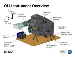
THEMIS Instrument Test Review Instrument Verification Program Overview Ellen Taylor University of California - Berkeley. Overview. Performance and Environmental Verification Philosophy Requirement Development and Verification Process Mission Requirements Documents (MRD) Verification Status

E N D
THEMIS Instrument Test Review • Instrument Verification Program Overview • Ellen Taylor • University of California - Berkeley
Overview • Performance and Environmental Verification Philosophy • Requirement Development and Verification Process • Mission Requirements Documents (MRD) Verification Status • Environmental Test Matrix (ETM) Verification Status • Instrument Performance Verification • Instrument System MRD Verification • Instrument MRD Verification Summary • Instrument Environmental Verification • Instrument Integration and Environmental Test Overview – Jeremy McCauley • Vibration Test Plans, Test Levels and ETU Test Results – Paul Turin • Thermal Test Plans, Test Levels and ETU Test Results – Chris Smith • EMC/MAG Test Plans, Test Levels and ETU Test Results – Michael Ludlam • Instrument Reliability and Quality Assurance – Ron Jackson • EEE Parts Status – Ron Jackson • Failure Reporting – Ron Jackson • Instrument Test Procedures • Reliability Analyses (FTA, FMEA, PRA) Status
Requirement Development and Verification Process • Top-Level requirements developed during Phase A • Concept Study Report (CSR) provides basic mission concept • Outlines top-level requirements imposed by science and programmatic objectives • Mission requirements flown down (to subsystem level), formalized and documented early in Phase B • All elements of CSR concept and mission requirements reviewed by development team • Mission Requirements Database (MRD) developed and reviewed • MRD finalized and put under Configuration Control at System Requirements Review (SRR), July 2003 • Subsystem Interfaces and Component Requirements further detailed in Phase B • Interface Control Documents between Subsystems and Institutions • System and Subsystem Specifications (Board Specifications, SOWs, etc) • Mission Plans and Policies (PAIP, Risk Management Plan, FMECA, etc) • Control Plans (Magnetics, ESC, Contamination)
Requirement Development and Verification Process • Requirement Verification Plans developed in Phase B and C • Development of Verification Matrix ensures a test or analysis is scheduled for all Mission Requirements in MRD • Performance Verification and Environmental Test Plans provide launch and space environments and outlines comprehensive component, subsystem and system level test program • Environmental Test Matrix (ETM) developed • Requirements Compliance and Verification Matrices completed in Phase D • MRD and ETM evolve into summary of verification and test program as run • Documents Verification and Compliance Status of all Requirements • Provides direct trace-ability from requirements to test procedures and reports
Performance Verification • Performance Verification Program • Applies to all technical requirements stated in MRD and associated documents • Each item in MRD has field for verification method • Performance Verification Methodology • Verification of requirements is by Inspection (I), Analysis (A), Test (T) or combination • Tasks for each method include: establishing the criteria; preparing plans and procedures; implementing; and documenting the results. • Performance Verification Levels • Verification will be performed at one or more of following levels: Component, Sub-Assembly, Assembly, Subsystem, System • Example from THEMIS MRD Verification Matrix:
MRD Status Mission Requirements Document (MRD) Status • MRD Rev A released at System Requirements Review (SRR) • MRD Rev B released prior to Instrument and Subsystem Peer Reviews • MRD Rev C released at Mission PDR • MRD Rev D released during Instrument and Subsystem Peer Reviews • Incorporated MPDR RFAs and System Change Notices (SCNs) since PDR • Added compliance and detailed verification plan (I/A/T) for each requirement • MRD Rev E released at Mission CDR • MRD Rev F will be released at Mission PER • Working version of Rev F is used to track verification status of all requirements • Most Instrument performance requirements have been verified during the ETU development and test w/ all instruments meeting or exceeding required performance • One waiver is expected for Instrument requirements – SST exceeds magnetic budget allocation
Environmental Verification • Environmental Test Program • Instrument hardware is tested to environmental requirements using GEVS as a Guideline per CDRL THM-SYS-005 THEMIS Instrument Payload Verification and Environmental Test Specification and summarized in Environmental Test Matrix (ETM) • Environmental Test Methodology • Each hardware item in ETM has fields for test description, test date, and procedure/report • Applies to all instrument assemblies, subsystems and systems • Example from THEMIS Environmental Test Matrix:
ETM Status Environmental Test Matrix (ETM) Status • ETM presented at Mission CDR and delivered to GSFC as CDRL • ETM has been further reviewed with minor changes to overall plan • No changes at the Instrument or Instrument Suite Level • ETM has evolved into summary of test program as-run • Working version is used to track test status of all instrument systems • Most Instruments have successfully completed all environmental tests on ETUs • ETU Mag Booms have not gone through Thermal Vacuum Testing – expected mid December • ETU ESA has not gone through Thermal Vacuum Testing – planned for flight unit only due to heritage
Instrument MRD Verification • MRD Instrument Payload Requirements • Lifetime and Radiation • Resource Budgets • Thermal • Contamination • Interfaces • Test and Verification • MRD Instrument Requirements • Status of Science Calibration • Performance Tests Completed and Planned • MRD Performance Verification • Changes from ETU to Flight to Improve Performance
Mission Manager Frank Snow, GSFC Project Scientist D. Sibeck, GSFC Launch Vehicle G. Skrobott, KSC THEMIS PI V. Angelopolous, UCB Science Co-I’s EPO N. Craig, UCB Project Manager P. Harvey, UCB Quality Assurance R. Jackson, UCB Scheduling D. Meilhan, UCB Financial Mgr K. Harps, UCB Subcontracts J. Keenan, UCB Mechanical/ Thermal Systems P. Turin, UCB C. Smith, UCB Mission Systems E. Taylor, UCB Probe/Probe Carrier Management UCB Oversight: D. King Swales Mgr: M. Cully Instruments M. Ludlam, UCB Software Systems D. King, UCB Mag Cleanliness C. Russell, UCLA Mission I&T J. McCauley, UCB Ground Segment M. Bester, UCB Organization
Instruments Instrument Data Processor Unit (IDPU) M. Ludlam Electric Field Instrument (EFI) J. Bonnell ElectroStatic Analyser (ESA) C. Carlson Solid State Telescope (SST) D. Larson Fluxgate Mag (FGM) U. Auster Search Coil Mag (SCM) A. Roux Robert Abiad Peter Berg Heath Bersch Dorothy Gordon Frank Harvey Selda Heavner Jim Lewis Jeanine Potts Chris Scholz Nestor Castillo Forrest Mozer Greg Delory Art Hull Bill Donakowski Greg Dalton Robert Duck Mark Pankow Dan Schickele Stu Harris Hilary Richard M. Marckwardt Bill Elliott Ron Herman Chris Scholz Heath Bersch Robert Lin Davin Larson Ron Canario Robert Lee T. Moreau TUBS/IWF Uli Auster K.H. Glassmeier W. Magnes CETP Alain Roux Bertran de la Porte Olivier Le Contel Christophe Coillot Abdel Bouabdellah Mag Booms LASP Robert Ergun Aref Nammari Ken Stevens Jim Westfall Hari Dharan Y. Kim Tien Tan Bill Tyler Organization
Lifetime and Radiation • Status • Initial GSFC Radiation Analysis complete. See Table 2 from report below. • Environment < 33 krad for all instruments except ESA (81.5 krad) • Additional electronics shielding added to ESA • 100% Instrument Parts screened for TID/SEE requirements. Approx. 20 parts were tested. • No parts that failed radiation testing are being used • LVPS redesign required - reduced supply efficiency
Resource Budgets - Mass • Status • Approx. 93% of ETU Instrument Payload has been weighed • Thermal blankets and Flight cables are estimated CBE: 23.19 kg Allocation: 23.63 kg Contingency: 1.9%
Resource Budgets - Power • Status • Approx. 90% of ETU Instrument Payload power has been measured (all Instruments except ESA) • ~3x power increase between ETU and Flight Actels was estimated and additional resistor load put on 2.5V line for ETU system CBE: 14.27 W Allocation: 14.77 W Contingency: 3.5%
Resource Budgets - Data • Status • 187.5MB storage is required (750Mbits/orbit + 1 day contingency = 1500Mbits = 187.5MB) • DCB contains 256MB SDRAM for TM storage. Upper quadrant is devoted to ECC. • Memory analysis using predicted data rates from Instruments show storage is sufficient for 4 day orbit + 1day contingency at worse-case spin period of 2.7seconds.
Thermal Requirements • Status • ETU Instruments are tested to Thermal Limits +10 degrees • Flight Instruments are tested to Thermal Predicts +10 degrees • Most ETU Instruments have completed Thermal Vacuum Testing, with the exception of: • ETU Mag Booms – expected mid December • ETU ESA – planned for flight unit only due to heritage. ETU ESA Pre-Amp was tested in IDPU TV Test. ETU ESA Actuator was tested in separate Release Plate Assembly TV Test.
Contamination Requirements • Status • Worse-case offenders for Magnetics is EFI Booms, SST magnets, IDPU switching frequencies • ETU EFI Booms w/ mu metal shielding tested at UCLA, meets budget of 0.25 nT @ 2m • SST Magnets analysis and testing show it is extremely difficult to meet 1.25 nT @ 2m. Waiver likely. • IDPU frequency management plan has implemented in LVPS - switching frequencies above 100 kHz, separated by 10 kHz to avoid beet frequencies in science range. Noise measurements with SCM sensor were made first week of December 2004. Provisions for synchronization circuit suggested by SWRI implemented in flight LVPS layout, but implementation unlikely given initial SCM testing results.
Interface Requirements • Status • All ETU Instrument Boards (DAP, ETC, FGE, DFB, BEB) have been integrated and tested with ETU IDPU core system (LVPS, DCB and PCB) • Most ETU Instruments (SSTs, ESA Pre-Amp, EFI Pre-Amp, FGM, SCM, Boom Simulators) have been integrated and tested with ETU IDPU box (Core System and Instrument Boards) • Data Interface between IDPU and Probe BAU has been tested on 3 occasions (UCB-Swales I/F Tests: July, October, December). Various levels of interface verification completed during each test. Power Interface Test planned for January. • Mechanical Hi-Fi Instrument Mock-ups provided to Swales for Integration to Hi-Fi Probe. Mass Models to be provided to Swales for Structure Strength and Thermal Testing.
IDPU/Instrument ETU I&T ETU IDPU Thermal Vacuum Testing ETU IDPU Functional Testing
Verification and Test • Status • As provided in MRD and ETM and summarized during Review: • ftp://apollo.ssl.berkeley.edu/pub/THEMIS/1 Management/1.3 Systems Engineering/1. Requirements/thm_sys_001f_MRD.pdf • ftp://apollo.ssl.berkeley.edu/pub/THEMIS/1 Management/1.3 Systems Engineering/1. Requirements/thm_sys_005AppA_InstrumentETM.pdf
Instrument Science and Performance Requirements • Fluxgate Magnetometer (FGM) • Calibration Status: • 3 ETU’s completed • F4 & F6 test and calibration completed • F1, F2, F3, F5 test and calibration to be completed by February 2005 • Performance Tests performed on ETUs, F4 & F6: • digital functional test • analogue adjustment of FGS and FGE • temperature test of electronics • temperature test of sensor • test of non-linearity • Earth field registration • determination of sensor axis direction • determination of scale value and orthogonally • noise test
Instrument Science and Performance Requirements • Fluxgate Magnetometer (FGM) • Verification of MRD Requirements: • All MRD requirements verified on ETU and first flight units • Absolute Stability, Relative Stability, Noise Level, Resolution • Driving Requirement: • Changes to Flight design from ETU to improve performance: • AD648 to be replaced with LT1013 to improve Absolute Stability measurement • Grounding wire added and feed-back wires replaced with twisted/shielded wires IN.FGM-5 The FGM noise level @ 1Hz shall be less than 0.03nT/Sqrt(Hz)
Instrument Science and Performance Requirements • Search Coil Magnetometer (SCM) • Calibration Status: • ETU completed, Magnetic Calibration Facility Chambon-la-Foret • F1, F2, F3 test and calibration completed in December 2004 • F4, F5 test and calibration to be completed by February 2005 • Performance Tests performed on ETU: • Transfer function measurement • Calibration signal measurement (spectrum, waveform) • Noise and Sensitivity • Orthogonal measurement • Projection (angle between magnetic field source and magnetic axis)
Instrument Science and Performance Requirements • Search Coil Magnetometer (SCM) • Verification of MRD Requirements: • All MRD requirements verified on ETU • Transfer Function, Sensitivity, Orthogonality • Driving Requirement: • Changes to Flight design from ETU to improve performance: • None IN.SCM-3 The SCM sensitivity shall be better than 1pT/Hz^1/2 @10Hz , and 0.1 pT/Hz^1/2 @1 kHz.
Instrument Science and Performance Requirements • Solid State Telescope (SST) • Calibration Status: • ETU1 completed, ETU2 facility issues • F1 test and calibration December 2004 • F2, F3, F4, F5 test and calibration to be completed by January 2005 • Performance Tests performed on ETU: • digital functional test • analog functional test • temperature test of electronics • temperature test of sensor (noise testing over temperature) • magnetic cleanliness test and analysis • noise test • detection thresholds • energy thresholds • off-axis response (including information on the response to scattered particles) • dead time • electron and proton detection efficiency of individual counting rate channels • sun pulse recovery
Instrument Science and Performance Requirements • Solid State Telescope (SST) • Verification of MRD Requirements: • All MRD requirements verified on ETU • Resolution, Moments • Driving Requirements: • Changes to Flight design from ETU to improve performance: • Added capacitors to reduce noise and cross-talk • Flight detectors w/ improved performance characteristics • Changed baseline sun pulse recovery time (added digital logic) • Lowered operating temperature IN.SST-7The SST shall measure energetic particles over an energy range of 30-300keV for ions and 30-100keV for electrons found in the magnetotail plasma sheet . IN.SST-8The SST energy sampling resolution, dE/E, shall be better than 30% for ions and electrons.
Instrument Science and Performance Requirements • Electric Fields Instrument (EFI) • Calibration Status: • ETU completed • F1 test and calibration December 2004 (SPBs) • F1 test and calibration early January 2005 (AXB) • Performance Tests performed on ETU: • Quiescent and Operational Currents • DC Tests (Gain, Offset, CMRR, Linearity, 0.1% Matching) • AC Tests (Transfer Function, CMRR, Slew Rate, Linearity) • SPB - Deploy Length, Turns Count, Deploy Rate, Door Actuation, Door Function, Deploy Currents, Cable Continuity and Isolation • AXB - Deploy Length, Repeatability, Stiffness, Straightness, Deploy Current, Cable Continuity and Isolation • EFI/SCM/FGM via DFB Phase Intercalibration - performed using EFI Test/Enable Plugs, SCM Mu-Metal Box, FGM TCU and 12-channel, 16-bit, +/- 10-V National Instruments DAC system – TO BE COMPLETED THIS WEEK
Instrument Science and Performance Requirements • Electric Fields Instrument (EFI) • Calibration Status: • ETU completed • F1 test and calibration December 2004 (SPBs) • F1 test and calibration early January 2005 (AXB) • Performance Tests performed on ETU: • Quiescent and Operational Currents • DC Tests (Gain, Offset, CMRR, Linearity, 0.1% Matching) • AC Tests (Transfer Function, CMRR, Slew Rate, Linearity) • SPB - Deploy Length, Turns Count, Deploy Rate, Door Actuation, Door Function, Deploy Currents, Cable Continuity and Isolation • AXB - Deploy Length, Repeatability, Stiffness, Straightness, Deploy Current, Cable Continuity and Isolation • EFI/SCM/FGM via DFB Phase Intercalibration - performed using EFI Test/Enable Plugs, SCM Mu-Metal Box, FGM TCU and 12-channel, 16-bit, +/- 10-V National Instruments DAC system – TO BE COMPLETED THIS WEEK
Instrument Science and Performance Requirements • Electric Fields Instrument (EFI) • Verification of MRD Requirements: • All MRD requirements verified on first flight units • Resolution, Range, Noise Level verified • Driving Requirements: • Changes to design from ETU to improve performance: • None IN.EFI-11The EFI noise level shall be below 10^-4 mV/m/sqrt(Hz). IN.EFI-13The EFI shall achieve an accuracy better than 10% or 1mV/m in the SC XY E-field components during times of onset.
THEMIS Instrument Test Review • Integration and Environmental Test Program Overview • Jeremy McCauley • University of California - Berkeley
Overview • Agenda • Facilities Status – Integration and Environmental • Instrument I&T Flow • Instrument Suite I&T Flow • Current Status (PER topics)
Facilities - Integration • B20 Cleanroom • Suite Performance and Environment Testing
Facilities - Integration • RM 125 Cleanroom • Suite Integration and Electrical Verification
Facilities - Environmental Available Chambers Type Comment SLW HiBay L1 TV STEREO SLW HiBay L2 TV STEREO SLW 320 T10 TV STEREO SLW 320 Cal Vac ESA Cal • Thermal Chambers • Space Sciences Lab • New Chamber for EFI Booms • Cal Chamber Upgrade for SST • Vibration Facilities • Quanta Labs • EMI/EMC • EMCE Engineering – Freemont SLW 320 “Mini” TV SCM, Bake-outs SLW B20-TV “Bayside” TV EFI PA, SPB, IDPU SLW B20-Large TV TV Payload TV SLW B20-Cal VAC2 Vac SST Cal AXB, SST SLW B20-TV “Snout” TV ESA MCPs SLW 339-TV Cal
Status – TV Facilities • Bayside Chamber • Currently supporting thermal vacuum needs • IDPU ETU • EFI PA ETU and F1-F3 • SPB ETU and subassemblies
Status – TV Facilities • Bertha Chamber • In final stages of assembly • Undergoing TC calibration • Undergoing bakeout with TQCM and RGA monitoring • Current baseline 242Hz/hour at 50°C • Ready for ETU Suite test by January 1
Status – TV Facilities • Snout Chamber • In final stages of assembly • Undergoing TC calibration • Undergoing bakeout with TQCM and RGA monitoring • Ready for AXB ETU test by December 13 • Cal Chamber • Currently supporting SST calibration
Instrument (EFI) I&T Flow EFI Pre-Amp Functional EFI Pre-Amp Thermal EFI Pre-Amp Delivery EFI PRE-AMP • Swales Spec • 2 cycles SPB/Pre-Amp Functional SPB PER SPB Vibration SPB Thermal SPB Delivery EFI RADIAL BOOM (SPB) • Swales Spec • 2 cycles T-V • Hot/Cold Deploy AXB/Pre-Amp Functional AXB PER AXB Vibration AXB Thermal AXB Delivery EFI AXIAL BOOM (AXB) • Swales Spec • 2 cycles T-V • Hot/Cold Deploy EFI ELECTRONICS (BEB and DFB) BEB Acceptance IDPU Safe-to-Mate EFI Functional (Level 0) IDPU/ESA PER IDPU/ESA/ SCM Pre-Amp Vibration IDPU/ESA Thermal IDPU/ESA Delivery • Backplane • Swales Spec • 2 cycles T-V DFB Acceptance • Without sensors
F1 Instrument Suite I&T Flow Harness Bake-out IDPU-Harness Safe-to-Mate FGM Functional (CPT) SST Functional (CPT) EFI Functional (LPT) EFI SPB Deploy • Jan 3-4 • ETU IDPU • Jan 5-6 • Jan 7-10 • Jan 11-12 EFI Functional (CPT) SCM Functional (CPT) Mag Boom Deploy Mag Alignment EFI AXB Deploy • Jan 13-14 • Jan 17 • Jan 18-19 • Jan 20 • Jan 21 ESA Functional (CPT) Payload CPT EFI/SCM/FGM Phasing Flight IDPU Integration Payload Self-Compat • Jan 24 • Jan 25-26 • Jan 27-28 • Jan 31 - Feb 1 • Feb 2 Instrument PER Payload EMI/EMC/MAG Payload Thermal Payload Vibration Payload Acceptance (PSR) • Workmanship • (if necessary) • Feb 24 • Feb 9 • (1 week slack) • Feb 10-16 • Feb 17-23 • Instrument Suite I&T in order of Instrument Delivery schedule • Based on 5 day work weeks, week-ends considered slack • 1 week slack between finish of Electrical Integration and beginning of Instrument Environmentals • Instrument Suite PSR 3/14/05
Integration Set-up Instruments at SSL integrated on platform same form factor as probe INSTRUMENT PAYLOAD ASSEMBLY PLATE
Instrument Delivery to SC • Schedule – Instrument Payload Delivery • P1: 3/14/05 (Instrument PSR) • P2: 4/19/05 • P3: 4/19/05 • P4: 5/25/05 • P5: 5/25/05With each instrument suite we deliver harnesses, GSE computer, booms, sensors in protection boxes. • Support Instrument GSE • Purge equipment including tubing and regulator • Degausser • Magnetometer • Oxygen sensor
Flight Instrument Status • Instrument Environmental Testing - Board level screening - PER 12/1/04 X – Completed, T – Test in Progress
Flight Instrument Status • Instrument Environmental Testing – PER • Required prior to environmental testing of flight units • Topics covered include: • Status of the Flight Instrument: • A flow chart of testing activities • Review of travelers and QA assessment • List of outstanding deviances from the final flight configuration (electrical substitutions, mechanical checks, etc.; responsible party) • Functional tests passed and documented • Assure the unit meets all functional requirements as posed in the MRD • Assure contamination and cleanliness precautions are sufficient • Status of Procedures: Vibration Test Procedure, Thermal Vacuum Cycling Procedure, LPT and CPT procedures
Flight Instrument Status • Instrument Environmental Testing – PER • Topics covered include: • Related Risks: • Outstanding ETU tasks • Status of action items from previous reviews • Facilities: • Is there a suitable spot in the facilities schedule for these test in the near future? • Is the Facilities Team able to support this test? (resources, configuration, personnel)
THEMIS Instrument Test Review • Vibration Test Program • Paul Turin • University of California - Berkeley
Vibration Testing • Flight Instruments undergo sine and random vibration testing to the levels called out in Swales TM-2430-RevD6 per UCB Instrument Test Procedures • ETUs were tested to the levels called out in Swales TM-2508, TM-2510, and TM2575-2 • Updated levels in TM-2430 have somewhat higher Grms levels but reflect a redistribution to higher ASD levels at low frequencies where motion is all rigid body, and lower levels at the 100-300 Hz peak. Thus, Swales does not feel we need to retest any instruments. • Each test is preceded and followed by a 0.5g sine survey • Each test is compared for significant shifts in peak frequency • The minimum resonant frequency required for THEMIS instruments is listed below. This will be verified during the sine surveys.
ETU Testing IDPU/ESA ETU SST ETU