Download
1 / 21
210 likes | 257 Views
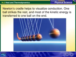
Microscopic Model of Conduction. Microscopic Model of Conduction. From Earlier: Electric Current. Figure: Assume charges are moving perpendicular to a surface of area A . Δ Q is the amount of charge that passes through A in time Δ t . So, the average current is defined as:.

E N D
Microscopic Model of Conduction From Earlier: Electric Current • Figure: Assume charges are moving perpendicular to a surface of area A. • ΔQ is the amount of charge that passes through A in time Δt. So, the average currentis defined as: • If the rate at which the charge flows varies with time, the instantaneous current, I, is defined as the differential limit of the average current as Δt→0:
Direction of Current • The charged particles passing through the surface could be positive, negative or both. • As already mentioned, it is conventional to assign to the current the same direction as positive charges would flow. • So, in an ordinary conductor, the direction of current flow is opposite the direction of the flow of electrons. It is common to refer to any moving charge as a charge carrier.
Current and Drift Speed • See Figure: Consider again a model in which charged particles move through a cylindrical conductor of cross-sectional area A. Define: n Number of mobile charge carriers per unit volume. • Consider the small volume Ax shown in the figure. nAΔxTotal number of charge carriers in that volume. • The total charge in that volume is the number of carriers times the charge per carrier, q: ΔQ = (nAΔx)q
The total charge in the small volume isΔQ = (nAΔx)q • Assume the carriers move with velocity parallel to the axis of the cylinder so that they are displaced in the x-direction. • If vd is the speed at which the carriers move, then • vd = (Δx/Δt) & x = vdt • Rewritten, ΔQ becomes: • ΔQ = (nAvdΔt)q • So, the average current is: • Iave = ΔQ/Δt = nqvdA • vdis an average speed called the drift speed.
Charge Carrier Motion in a Conductor • See Figure: When a potential difference is applied across the conductor, an Electric field is set up in it, which exerts an Electric Force on the electrons. • The motion of the electrons is no longer random. The zigzag black lines represent the motion of a charge carrier in a conductor in the presence of an electric field.
Charge Carrier Motion in a Conductor For electric fields, that are not too large, the net drift speed is small. • The sharp changes in direction are due to collisions. The net motion of electrons is opposite the direction of the electric field.
Motion of Charge Carriers, cont. • In the presence of an electric field, in spite of all the collisions, the charge carriers slowly move along the conductor with a drift velocity, vd • The electric field exerts forces on the conduction electrons in the wire. • These forces cause the electrons to move in the wire and create a current. • The electrons are already in the wire. They respond to the electric field set up by the battery. • The battery does not supply the electrons, it only establishes the electric field.
Drift Velocity, Example • Assume a copper wire, with one free electron per atom contributed to the current. • The drift velocity for a 12-gauge copper wire carrying a current of I = 10.0 A is 2.23 10-4 m/s • This is a typical order of magnitude for drift velocities.
Current Density • J is the current densityof a conductor. It is defined as the current per unit area. J ≡ I / A = nqvd • This expression is valid only if the current density is uniform and A is perpendicular to the direction of the current. J has SI units of A/m2 • The current density is in the direction of the positive charge carrier motion.
Conductivity • A current density J & an E field are established in a conductor whenever a potential difference is maintained across the conductor. • For some materials, the current density is directly proportional to the field. • The constant of proportionality, σ, is called the conductivity of the conductor.
Ohm’s “Law” (microscopic version) • Ohm’s “Law”states that in many materials, the ratio of the current density to the electric field is a constantσthat is independent of the electric field producing the current. • Many metals obey Ohm’s law Mathematically, J = σ E
Ohm’s “Law” (microscopic version) Ohm’s “Law”:J = σ E • Materials that obey Ohm’s law are said to be Ohmic • Not all materials follow Ohm’s law. • Materials that do not obey Ohm’s law are said to be nonohmic. • Ohm’s law isn’t a law of nature. • It is an empirical relationship valid only for certain materials.
Resistivity • The inverse of the conductivity is the resistivity: ρ = 1 / σ • Resistivity has SI units of ohm-meters (Ω . m) • Resistance is also related to resistivity:
Resistance & Resistivity, Summary • Every ohmic material has a characteristic resistivity that depends on the propertie of the material & on the temperature. • Resistivity is a property of substances. • The resistance of a material depends on its geometry and its resistivity. • Resistance is a property of an object. • An ideal conductor would have zero resistivity. • An ideal insulator would have infinite resistivity.
Electrical Conduction – A Model • Treat a conductor as a regular array of atoms plus a collection of free electrons. • The free electrons are often called conduction electrons. • These electrons become free when the atoms are bound in the solid. • In the absence of an electric field, the motion of the conduction electrons is random. • Their speed is on the order of 106 m/s.
When an electric field is applied, the conduction electrons are given a drift velocity. Assumptions: • The electron’s motion after a collision is independent of its motion before the collision. • The excess energy acquired by the electrons in the electric field is transferred to the atoms of the conductor when the electrons & atoms collide. • This causes the temperature of the conductor to increase.
Conduction ModelCalculating the Drift Velocity • The force experienced by an electron is • From Newton’s 2nd Law, the acceleration is l • Applying a kinematic equation • Since the initial velocities are random, their average value is zero.
Let tbe the average time interval between successive collisions. • The average value of the final velocity is the drift velocity. • This is also related to the current density: J = nqvd = (nq2E / me)t n is the number of charge carriers per unit volume.
Using Ohm’s Law, expressions for the conductivity and resistivity of a conductor can be found: • Note, according to this classical model, the conductivity & resistivity do not depend on the strength of the field. • This feature is characteristic of a conductor obeying Ohm’s Law.