Download
1 / 3
30 likes | 115 Views
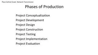
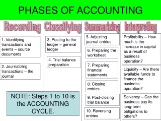
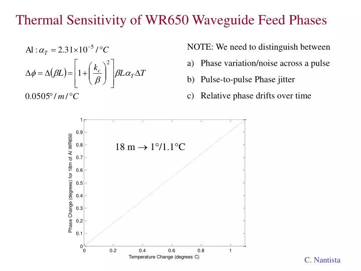
Thermal Sensitivity of WR650 Waveguide Feed Phases. NOTE: We need to distinguish between Phase variation/noise across a pulse Pulse-to-pulse Phase jitter Relative phase drifts over time. 18 m 1 ° /1.1 ° C. C. Nantista. RF Feeding Schemes from Klystron to 3 Cryomodules. td1.

E N D
Thermal Sensitivity of WR650 Waveguide Feed Phases • NOTE: We need to distinguish between • Phase variation/noise across a pulse • Pulse-to-pulse Phase jitter • Relative phase drifts over time 18 m 1°/1.1°C C. Nantista
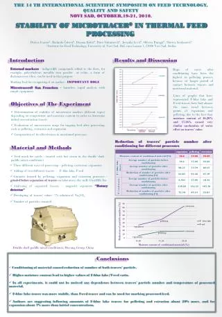
RF Feeding Schemes from Klystron to 3 Cryomodules td1 With a cavity fill time of hundreds of microseconds and bunch spacing of 337ns, the timing differences here of tens of nanoseconds are not particularly significant. Σ|td|/3 vg/c = 0.7157 P = ~11.4 m P/c = ~38 ns P/vg = ~53 ns P/vg - P/c = 0.3972 P/c = ~15 ns P/vg + P/c = 2.3972 P/c = ~91 ns td3 td2 Waveguide Length Total Difference downstream 0 ns 15 ns -15 ns 3 P 2 P least waveguide 0 ns (-35.3 ns) 15 ns (-20.3 ns) 91ns (55.7ns) 2 P P equal lengths 3 P 0 -38 ns 0 ns 38 ns minimized average delay 2.79 P 1.574 P 0.213 P 7.56 ns -7.56 ns 0 ns C. Nantista
Thermal Sensitivity of WR650 Waveguide Feed Phases Hi Chris, The cost estimating I did was more exploratory than fact-based. The higher number was based on loosely on retail cost for parts from either catalogs, talking with vendors, or simply based on my own experience buying things. Understanding that this first number was high, it helped me bound the problem and also determine relatively what the high cost drivers were. The lower cost I arrived at by literally by "slashing prices" on components. I did this again as an exercise to try and bound the problem, and the numbers are not based on actual costs of anything per se or models for cost savings. I looked at a given part, thought about how cheap I could possibly conceive of buying this part if it was mass produced and some clever people thought of nice ways of simplifying production, and put in that number. The alarming thing to me was some of the piece part numbers I put in seemed outrageously low (like ~1k$ for a high power 3 stub tuner in WR650), yet the cost total was still higher than desired, due mainly to the extensive numbers of parts involved. The klystron and modulator costs were pulled right out of the FNAL cost report I showed in the presentation, and I didn't mess with them. Overall, the major basis of the cost estimates was my personal experience of costing and building up a few high power RF systems in my career. The main point of the work was to come up with relative rankings of cost drivers and to raise the awareness that 250,000 of anything is a big number. So, moving on to the next step of getting more accurate costs seems like the right thing to do. BR