Download
1 / 23
230 likes | 405 Views
One Arm Cavity. QUAD. M0. TRIPLE. L1. M0. L1. L2. 16m. L2. TM. R = ∞, T=1%. R = 20m, T=1%. Optimally coupled cavity (no mode matched light reflected back) Finesse ~ 625. Goals. QUAD TESTING: Electrostatic Drive (ESD) Hierarchical Control Lock Acquisition. ESDs.

E N D
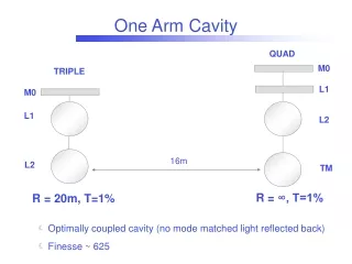
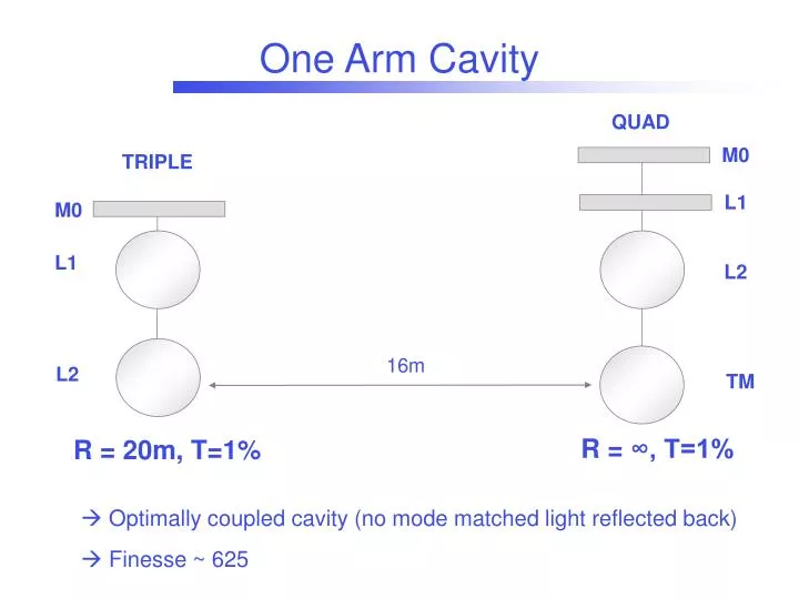
One Arm Cavity QUAD M0 TRIPLE L1 M0 L1 L2 16m L2 TM R = ∞, T=1% R = 20m, T=1% • Optimally coupled cavity (no mode matched light reflected back) • Finesse ~ 625
Goals • QUAD TESTING: • Electrostatic Drive (ESD) • Hierarchical Control • Lock Acquisition
ESDs 4 pairs of gold electrodes, coated onto the reaction mass Each pair of electrodes forms a capacitor, which attracts the mirror surface (dielectric) placed in front of it Bias, Control LASTI Q2 Q1 Q3 Q4 The attractive force F is proportional to the square of the applied voltage V F = (r, dx,a)V² Constant geometry factor depending on the electrode pattern design distance between test mass and reaction mass
Design for Advanced LIGO - I Electrostatic drive (ESD) results from GEO and application in Advanced LIGO T060015-00-K, K. Strain (Feb 2006) Coupling coefficient a [N/V²] expected* to be: = 7e-10 N/V² * Measured in GEO (4.9e-10 N/V²), for Advanced Ligoestimate of 35% more force produced for a given voltage thanks to a different electrode pattern Maximum force available for lock acquisition (with a difference of 800 V between the two channels): FMAX = 7e-10 * (800)² = 450
LASTI Measurement - I BIAS driven with an offset and CONTROL with a sine wave having same amplitude as the offset component 2 component With a 7Hz line, taking into account the controller and the 1/f² F -> POS transfer function, we expect the component (7Hz) to be twice as big as the 2(14 Hz)…. …but component not measured at all!!
LASTI Measurement - II By driving a single electrode with an OFFSET plus a SINE, we get what we expect (similar results for all of the 8 electrodes): SINE on controls + OFFSET on BIAS SINE + OFFSET on a single electrode
What’s the problem? It looks like each electrode driven by itself gives the expected response, but it doesn’t “see” its pair.. Possible explanation: the metallic part standing in for the QUAD mirror changes the behavior of the electric field between the ESD electrodes and the test mass, ( fringe field is not dominant anymore) TEST MASS
LASTI Numbers Cavity error signal calibration: 2e6 counts/ mm 610 V/mm Coupling coefficient a measured by driving ALL the electrodes with V = 110 +110*sin(wt): V² = 52N 2.15e-9 N/V² Measured coupling coefficient about a factor 3 bigger than the expected one for Advanced LIGO, but maximum voltage difference available about 2.5 smaller (300V instead of 800V) Maximum force available for lock acquisition FMAX = 2e-9 * (300)² ~ 180 2.5 times less force available than the Advanced LIGO design
ESD Linearization - Code VOLTAGE FORCE
Normalized Error Signal ESD Drive - I When the cavity is kept locked acting on the triple, the pk-pk correction sent to the OSEM is about 4000 counts, which is equivalent to: The corrections which we need to send to the ESD are too high: ~100 Hz/sqrt(Hz) @ 100 Hz Correction Signal * NPRO Laser frequency noise specifications not available, expected about 100 times less
Frequency Noise Reduction Phase-lock loop: NPRO frequency stabilized to the PSL (via-fiber) Frequency noise reduced by about a factor 10
ESD Linearization - Efficiency Better evaluation of the efficiency of the linearization code ESD driven @ 7 Hz Reduction by about a factor 10 of the first harmonic
ESD Drive - II GOAL: keep the cavity locked using the ESD-quad above 20-30 Hz and the OSM-triple below Not more than 25% change in the open loop TF of the longitudinal loop (both OSM-triple and ESD-quad drive) measured with the “right” (blue) and “wrong” (red) sign of the ESD loop The ESD can’t be used to keep the ITF locked yet, at least a factor 10 less frequency noise needed
QUAD “Hierachical Control” QUAD - L2 below 10 Hz, Triple above Error Signal Correction Signal
Test Mass Charge: ESDs as Sensor Top Mass of the QUAD (M0) driven at 2.5 Hz 4 electrodes of the ESDs used as sensors, connected as input signal to an SR560 BSC ground connected to the SR560 ground
Test Mass Charge: ESDs as Sensor What seen by the L2 sensors
Summary • ESD: not behaving according to the design • frequency noise too big to used them for keeping the cavity locked • linearization code tested, works properly • Cavity controlled below 10 Hz acting on the QUAD-L2 (“Hierarchical Control”)
Plans Improve frequency stabilization (get rid of the fiber?) Technical problems to be discussed: space for a new input bench, … Tests on QUAD Noise Prototype (ESD, Hierarchical control, Lock Acquisition)
OFFSET+SINE on all the electrodes OFFSET+SINE on controls –(OFFSET+SINE) on BIAS Measurement - III • All of the 8 electrodes driven with an OFFSET plus a SINE No significant difference measured in the amplitude of the component by inverting the sign of the drive on the BIAS HARMONIC COEFFICIENTS
BLU: right sign RED: wrong sign ESD Drive - I • When the cavity is kept locked acting on the triple, the pk-pk correction sent to the OSEM is about 4000 counts, which is equivalent to: • The impact of the ESD is of the order of 5% (maximum gain applicable without saturating the actuators): Open loop TF of the longitudinal loop (both OSM-triple and ESD-quad drive) measured with the “right” and “wrong” sign of the ESD loop The ESD can’t be used even to keep the ITF locked
ESD Drive - II Difference between the drive configurations not even noticeble in the power spectra.. ..except for a resonance which gets excited when driving the ESD (with the right sign).
Problems • With the current optical set-up, the frequency noise is still too high (~10 Hz/sqrt(Hz) @ 100 Hz), at least a factor 10 times less noise needed • PSL should provide ~ 0.05 Hz/sqrt(Hz) above 500 Hz (Any Measurement available?) and with the phase lock loop on we should get the same performance as with the PSL. Are we limited by the fiber (acoustic noise, ..)? • The RMS of the cavity error signal is dominated by structures around 100-300 Hz. Where do they come from? ( Mechanical resonances of optical components in the region 400-700 Hz. Acoustic noise coupling)