Download
1 / 46
460 likes | 545 Views
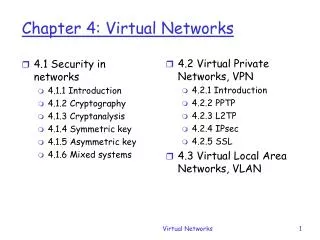
COMP/ELEC 429 Introduction to Computer Networks. Lecture 23: Overlay networks Slides used with permissions from Edward W. Knightly, T. S. Eugene Ng, Ion Stoica, Hui Zhang. Abstract View of the Internet. A collection of IP routers and point-to-point physical links connecting routers

E N D
COMP/ELEC 429Introduction to Computer Networks Lecture 23: Overlay networks Slides used with permissions from Edward W. Knightly, T. S. Eugene Ng, Ion Stoica, Hui Zhang
Abstract View of the Internet • A collection of IP routers and point-to-point physical links connecting routers • Point-to-point links between two routers are physically as direct as possible • A copper wire, a coax cable or a fiber laid from one router to another
Reality • Fibers and wires are laid with tremendous physical constraints • You can’t just dig up the ground everywhere and lay fibers • Right-of-way issue • Most fibers are laid along railroads • Physical fiber topology often very far from the topology you want • IP Internet is over-laid on top of this physical fiber topology • IP Internet topology is only logical! • Concept: IP Internet is an overlay network
IP logical link Circuit E.g. An IP logical link overlaid on a circuit
Made Possible by Layering • Layering hides the detail of lower layer from higher layer • IP operates on datalink layer (say ATM or SONET) logical topology • ATM/SONET creates point-to-point circuits on the fibers Host A Host B Application Application Presentation Presentation Session Session Router Transport Transport Network Network Network Datalink Datalink Datalink Physical Physical Physical Physical medium
Overlay • Overlay is clearly a general concept • You can keep overlaying one network on another, it’s all logical • IP Internet overlays on top of physical topology • Why stop here? • Something else can overlay on top of IP Internet • Use IP tunnels to create yet another logical topology • E.g. VPNs
Advanced Reasons to Overlay On IP Internet • IP provides basic best effort datagram service • Many things you may want in a network but not supported • Like what? • Multicast • Reliable performance-based routing • More… e.g. content addressing and distribution • Can you build can overlay network on IP Internet to provide QoS? • How? • Overlay links must have guaranteed performance characteristics, otherwise, the overlay network cannot guarantee anything!
Unicast Routing Overlay • Internet routing is built upon Intra-domain and Inter-domain router protocols • OSPF/RIP; BGP • OSPF/RIP routing based on shortest link weight routing • Link weights are typically very static • Does not necessarily give you best performance path (delay, throughput, loss rate) • BGP routing based mostly on policy • Policy may have nothing to do with performance • BGP very slow to react to failure (no reaction to high loss rate, e.g.)
Resilient Overlay Network (RON) • Install N computers all over the place on the Internet • Each computer acts as an overlay network router • Between each overlay router is a IP tunnel (logical link) • Logical overlay topology is all-to-all (N^2) • Computers actively measure each logical link in real time for • Packet loss rate, latency, throughput, etc • Route overlay network traffic based on measured characteristics • Able to consider multiple paths in addition to the default IP Internet path given by BGP/OSPF
Reroute traffic using red alternative overlay network path, avoid congestion point Example Acts as overlay router Default IP path determined by BGP & OSPF 1
Potential Problems… • Scalability of all these network measurements! • Overhead • Interference of measurements? • What if everyone has his/her own overlay network doing this? • Stability of the network? Oscillation? Keep rerouting back and forth? • How much can you really gain? • In delay/bandwidth, may not be that much • But is much faster to react to complete link failures than BGP
Multicast Overlay • IP multicast supposed to provide one-to-many packet delivery • IP multicast routers supposed to maintain group membership, duplicate packets appropriately and send to all members • Why “supposed”? In the Internet today, we have none of that
Solution based on Unicast • Client-server architecture (the Web) • Does not scale well with group size • Source host is the bottleneck Stanford Gatech CMU (Source) Berkeley
Overlay Tree Gatech Stan-LAN Stan-Modem CMU Berk1 Berk2 End System Multicast CMU Stan-LAN Stanford Gatech Stan-Modem Berk1 Berkeley Berk2
End System Multicast: Benefits • Scalability • Routers do not maintain per-group state • Easy to deploy • Works over the existing IP infrastructure • Can simplify support for higher level functionality CMU Transcoding Stan-LAN Unicast congestion control Berk1 Gatech Stan-Modem Berk2
Challenge to construct efficient overlay trees Performance concerns compared to IP Multicast Increase in delay Bandwidth waste (packet duplication) Stanford Stanford-LAN Gatech Gatech Stanford-Modem CMU CMU Berkeley Berk1 IP Multicast Berk2 Concerns with End System Multicast End System Multicast
More Challenges Stan-LAN Gatech Stan-Modem CMU Berk1 Berk2 Overlays must adapt to network dynamics and congestion Stan-LAN Gatech Stan-Modem CMU Berk1 Berk2 Group membership is dynamic: members can join and leave
CMU CMU Stan2 Stan2 CMU Stan-LAN Stan1-Modem Stan1-Modem Stan-Modem Gatech Berk1 Gatech Berk1 Berk1 Gatech Berk2 Berk2 Berk2 -Poor network usage -Potential congestion near CMU High latency Poor bandwidth to members Inefficient Overlay Trees
CMU Stan-Modem Stan-LAN Berk1 Gatech Berk2 An Efficient Overlay Tree
End System Multicast System • Focus on video broadcast applications • Implementation • Integrate with Apple QuickTime • Support for receiver heterogeneity • Support peers behind NAT and firewall • Run on Windows and Linux platforms • Showcase • SIGCOMM (max 60 simultaneous users) • Several CMU Distinguished Lectures • Slashdot (max 180 simultaneous users)
Adapt to Receiver Heterogeneity • Congestion control: hop-by-hop TCP • Determine acceptable data rate • Prioritization of data streams • Parent maintains a priority queue • Drop video packets before audio packets CMU 415Kbps MIT(Ethernet) Source rate(415Kbps) 415Kbps Berkeley(Ethernet) Stanford(wireless) 115Kbps
Interface with Application (QT) Mixer • Selects best viewable video stream dynamically • Switches between video streams for seamless playback A V (Loopback) Example: a peer with 2 children Mixer A V1 V2 Child 1 (TCP) ESM Protocol (TCP) Parent Child 2
Group Dynamics conference end lunch folks notactivelywatching? conference start 10am west coast
Overlay Tree at 2:09pm U.S. East Coast U.S. Central U.S. West Coast Europe Asia
Receiver Bandwidth (web download > 400Kbps are not shown)
Transient Performance: Outages Outage: loss rate exceeds 5% 95% of hosts have less than 3% outages for audio 3% outage: 2 second glitch every minute
Structured p2p overlays One primitive: route(M, X): route message M to the live node with nodeId closest to key X • nodeIds and keys are from a large, sparse id space
Distributed Hash Tables (DHT) nodes k1,v1 k2,v2 k3,v3 P2P overlay network Operations: insert(k,v) lookup(k) k4,v4 k5,v5 k6,v6 p2p overlay maps keys to nodes completely decentralized and self-organizing robust, scalable
Why structured p2p overlays? • Leverage pooled resources (storage, bandwidth, CPU) • Leverage resource diversity (geographic, ownership) • Leverage existing shared infrastructure • Scalability • Robustness • Self-organization
Pastry: Object distribution Consistent hashing[Karger et al. ‘97] 128 bit circular id space nodeIds(uniform random) objIds (uniform random) Invariant: node with numerically closest nodeId maintains object 2128-1 O objId nodeIds
Pastry: Object insertion/lookup 2128-1 O Msg with key X is routed to live node with nodeId closest to X Problem: complete routing table not feasible X Route(X)
Pastry: Routing Tradeoff • O(log N) routing table size • O(log N) message forwarding steps
Pastry: Routing table (# 65a1fcx) Row 0 Row 1 Row 2 Row 3 log16 N rows
Pastry: Routing Properties • log16 N steps • O(log N) state d471f1 d467c4 d462ba d46a1c d4213f Route(d46a1c) d13da3 65a1fc
Pastry: Leaf sets Each node maintains IP addresses of the nodes with the L/2 numerically closest larger and smaller nodeIds, respectively. • routing efficiency/robustness • fault detection (keep-alive) • application-specific local coordination
Pastry: Routing procedure if (destination is within range of our leaf set) forward to numerically closest member else let l = length of shared prefix let d = value of l-th digit in D’s address if (Rld exists) forward to Rld else forward to a known node that (a) shares at least as long a prefix (b) is numerically closer than this node
Pastry: Node addition d471f1 d467c4 d462ba d46a1c d4213f New node: d46a1c Route(d46a1c) d13da3 65a1fc
Node departure (failure) Leaf set members exchange keep-alive messages • Leaf set repair (eager): request set from farthest live node in set • Routing table repair (lazy): get table from peers in the same row, then higher rows
PAST: File storage fileId Insert fileId
k=4 fileId Insert fileId PAST: File storage Storage Invariant: File “replicas” are stored on k nodes with nodeIds closest to fileId (k is bounded by the leaf set size)
PAST: File Retrieval C k replicas Lookup file located in log16 N steps (expected) usually locates replica nearest client C fileId
SCRIBE: Large-scale, decentralized multicast • Infrastructureto support topic-based publish-subscribe applications • Scalable: large numbers of topics, subscribers, wide range of subscribers/topic • Efficient: low delay, low link stress, low node overhead
SCRIBE: Large scale multicast topicId Publish topicId Subscribe topicId