Download

1 / 11
110 likes | 213 Views
Oceanic Thermal Energy Conversions. Group Members: Brooks Collins Kirby Little Chris Petys Craig Testa. Problem Statement of Project.

E N D
Oceanic Thermal Energy Conversions Group Members: Brooks Collins Kirby Little Chris Petys Craig Testa
Problem Statement of Project To create and design an operating Oceanic Thermal Energy Conversion model that employs a closed Rankine Cycle that utilizes R22 as the working fluid to illustrate the viability of OTEC power production.
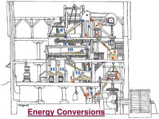
OTEC Model Organization Condenser cools vapor into liquid using water from a cold tank pumped through it (forced convection) Vapor turns turbine and power is produced with a generator Cycle begins again Working fluid is pumped into evaporator Evaporator turns the working fluid into vapor using water from a heated tank that is pumped through it (forced convection)
Pro-E Model Changes • This was our Pro-E model based on our project needs before we started ordering parts • When we began ordering parts, we realized that we were going to need to greatly change the Pro-E model of our system • We were able to greatly decrease the overall size of the system and fit it onto a single movable cart.
Design Differences: • Our new design fits on a movable cart with dimensions: 60” wide x 30” deep x 32” tall • Our heat exchangers are much smaller than previously expected with dimensions of 4” wide x 5” deep x 20” tall • We changed our tank design which is now a cylindrical tank design with a pre-plumbed hole that we connect to the circulation pumps
Progress this Semester • We have contacted Mr. Coleman at the CAPS building to acquire our security passes and a working area at the CAPS building. • We have began correspondence Dr. Greska at the FMRL to try and source a turbine that is sized for our application.
Ordered Parts • The following parts list will allow us to begin building the circulation systems for the cooling and heating systems. • We will order the condenser and evaporator, that were created specifically for our application, directly from Alfa Laval through Dr. Dave Cartes beginning next week when he returns back to FSU. • These parts will not factor into our budget set aside by the College of Engineering
Future Part Orders • We need to contact a local HVAC company in order to charge our system with R22 to our specified pressure.