Download
1 / 6

E N D
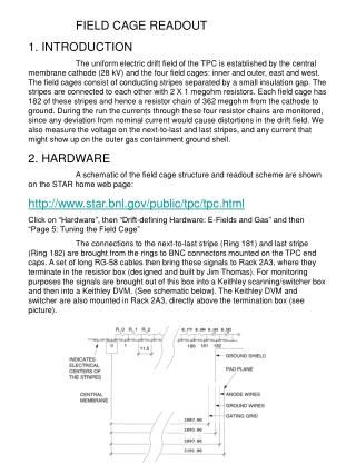
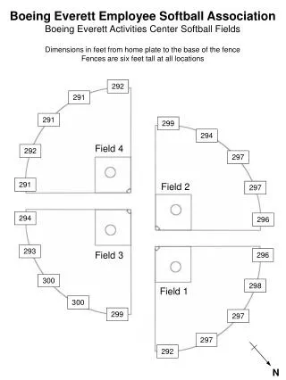
FIELD CAGE READOUT 1. INTRODUCTION The uniform electric drift field of the TPC is established by the central membrane cathode (28 kV) and the four field cages: inner and outer, east and west. The field cages consist of conducting stripes separated by a small insulation gap. The stripes are connected to each other with 2 X 1 megohm resistors. Each field cage has 182 of these stripes and hence a resistor chain of 362 megohm from the cathode to ground. During the run the currents through these four resistor chains are monitored, since any deviation from nominal current would cause distortions in the drift field. We also measure the voltage on the next-to-last and last stripes, and any current that might show up on the outer gas containment ground shell. 2. HARDWARE A schematic of the field cage structure and readout scheme are shown on the STAR home web page: http://www.star.bnl.gov/public/tpc/tpc.html Click on “Hardware”, then “Drift-defining Hardware: E-Fields and Gas” and then “Page 5: Tuning the Field Cage” The connections to the next-to-last stripe (Ring 181) and last stripe (Ring 182) are brought from the rings to BNC connectors mounted on the TPC end caps. A set of long RG-58 cables then bring these signals to Rack 2A3, where they terminate in the resistor box (designed and built by Jim Thomas). For monitoring purposes the signals are brought out of this box into a Keithley scanning/switcher box and then into a Keithley DVM. (See schematic below). The Keithley DVM and switcher are also mounted in Rack 2A3, directly above the termination box (see picture).
Picture 1: Bottom of Rack 2A3. The termination box is at the bottom of the picture. The two Keithley units are rackmounted side by side just above the termination box. The DVM is on the left, switcher on the right. The two large cables are the GPIB readout cables for the Keithleys, going from the VME crate (Rack 2A4) to the back of the Keithleys, inside the rack. The Keithley switcher consists of a “main frame”, model # 7001 with two scanner cards installed: a model 7054 High Voltage Scanner and a model 7158 low current scanner. The DVM is a model 2001 Multimeter. Under VME program control the units switch between each of the 5 currents and 8 voltages and measures each one. Since the dwell time is ~ 1 second per measurement, a cycle is completed ~ every 15 seconds. It is probably not advisable to go faster and still expect a stable measurement. One important thing to note about this system is that each of the four field cage resistor chains ALWAYS has a path to ground, both when it is switched to the DVM and when it is waiting. Also note that both ring 181 and 182 are connected to ground by a spark gap (these are inside at the BNC connector.) These sparks gaps have been selected to conduct at ~ 600 volts, so if the external ground is removed, the gaps will provide the path to ground and the field cage will not charge up to 28 kV. Note that this also has implications for placing external compensating resistors in the system (see section on shorts.
3. VME & GUI The processor for the field cage readout is in a VME crate in rack 2A4. The crate is Canbus address 56 and the processor is port 9001 on the serial server. The interface card is a dual output GPIB module, one output for the DVM and one for the scanner. To turn the system on, first turn on the DVM and scanner and then boot the processor. After the boot you should see the scanner display move from channel to channel and see the DVM measure 5 currents and 8 voltages at ~ 1 second intervals. The GUI for the field cage is accessible from the TPC top level GUI and is read only – there are no operations possible by the operator through the GUI. The GUI looks like: This shows the 4 field cage currents, the ground shell current, and the 8 voltages from rings 181 and 182. Note that the ground shell current readout is drowned in noise when the magnet is on – it is only useful for finding outer field cage coronas when the magnet is off. (In initial tests at LBL we had outer field cage corona above 35 kV. The corona provides a separate path to ground, so current would disappear from the resistor chain and appear on the ground shell – the ratio helps to locate the corona in z)
For alarm purposes we usually don’t look at the currents themselves, which can change with temperature and especially humidity. Rather, four calculated deltas are shown – each delta subtracts each measured current from the average of the other three. Alarm levels are then placed on these deltas to warn the operator if there is a short in any of the field cages. Note that one shorted stripe would result in a change in current of 420 nA out of 76 microamps. The screen capture shown above thus shows a field cage problem. During Run 8 the 4 currents were well behaved (except for a known OFCW problem), so the alarms on delta were set at ~ 200 nA. Offline studies have shown that a delta above ~ 100nA will cause distortions in the field cage that have a measurable effect on the data. In fact, for highest precision, the limit is even smaller. The OFCW problem has been happening for a few years – the current is bistable, and varies between nominal and nominal + 60nA. The offline program now tracks this variation and attempts to correct for it. There are also buttons on the GUI for popping up a scrolling display of the currents – I usually have one of these up for the inner and outer currents for the operators to watch during data taking and to allow me to scroll back to check for strange behavior over night. 4. FC SHORTS AND COMPENSATION Over the years we have encountered a few one stripe shorts, especially in the inner field cage. Gruesome history can be read in my notebooks. We have usually managed to find the reasons for these shorts (foreign objects left in the inner field cage), but they sometimes only show up after things are buttoned up and the magnet is turned on. We currently have one short in the IFCE, which has been made permanent – see the documentation by Alexei. We also have the above mentioned OFCW bistable problem – we have NOT attempted to go into the insulation gap area to try and locate this problem for fear of causing more problems. Past history shows that it is always a good idea to test the FC extensively as the detector is being brought on for a new data run, especially if work has gone on inside the IFC. Typically we test the FC daily until things are buttoned up and the magnet has been on at full field. A one stripe short can be somewhat compensated for by adding an external resistor to the corresponding resistor chain. This is done by putting a 2 Megohm (for one stripe) resistor inline at the termination box where the cable from stripe 181 goes into the box. Small boxes with various resistors have been made in advance and are stored inside Rack 2A3. 5. SPARES We have one spare Keithley multimeter, two spare scanner mainframes, one spare 7158 low current card and a refurbished 7054 HV card. The 7054 is no longer made by Keithley, but they sold us the encapsulated switch modules, and Ken Asselta installed them on our old card. The cards were replaced in March, 2003 when I was chasing some noise on the readout.
We do NOT have a spare dual output VME GPIB module. It is no longer made by National Instruments in the form we have. If the installed one fails we will have to do some slow controls work to either adapt a single output module by piggy backing the cables or use two singles in the same crate. Theoretically it should just be a GPIB addressing problem, but…. Given some spare time this could be worked on during shutdown times. 6. CANONICAL READINGS Aside from actual shorts in the field cage, the current and voltage readings will vary depending on conditions in the hall. The Keithley DVM is affected by humidity, so running in the spring and summer is difficult. (See page 21 in my logbook II). Also, the IFC readings are usually not reliable if the IFC air blower is not running and the IFC is open to the WAH air. Here are some canonical currents and voltages for ~ stable conditions: