Download
1 / 15
270 likes | 822 Views
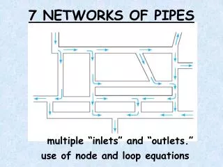
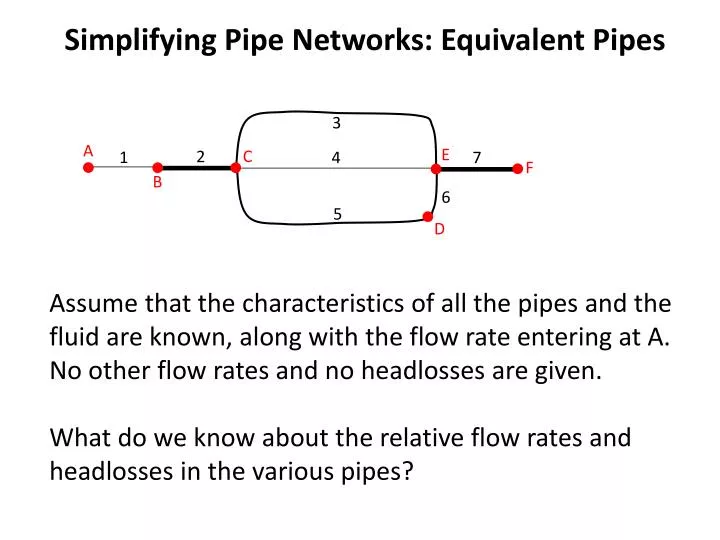
Simplifying Pipe Networks: Equivalent Pipes. 3. A. E. C. 2. 1. 4. 7. F. B. 6. 5. D. Assume that the characteristics of all the pipes and the fluid are known, along with the flow rate entering at A. No other flow rates and no headlosses are given.

E N D
Simplifying Pipe Networks: Equivalent Pipes 3 A E C 2 1 4 7 F B 6 5 D Assume that the characteristics of all the pipes and the fluid are known, along with the flow rate entering at A. No other flow rates and no headlosses are given. What do we know about the relative flow rates and headlosses in the various pipes?
3 A E C 2 1 4 7 F B 6 5 D By continuity: Q1=Q2=Q7=Q3+Q4+Q5, Q5=Q6 Because total head (z+[p/g]+V2/2g) has the same value at a point, regardless of direction (it is a scalar, and isotropic): hL,3=hL,4=hL,5+6 and (ShL)any loop=0
Flow Analysis in Systems with Multiple Pipes Two levels of complexity • One inlet, one outlet, flow directions known • Multiple inlets/outlets, flow directions need to be determined In both cases, key equations are the same • Continuity at junctions or nodes: total flow rate entering equals total flow rate leaving • Total head is well-defined at any point, so headloss between any two points is independent of path taken, and headloss around a loop is zero
3 A E C 2 1 4 7 F B 6 5 D IF the hL-Q relationship can be written as hL=KQn, then for m pipes connected in series, the total headloss when the flow rate is Q is: A pipe with K=SKi will be hydraulically equivalentto the real pipes in series.
3 A E C 2 1 4 7 F B 6 IF the hL-Q relationship can be written as hL=KQn, then for m pipes connected in parallel, the total flow rate when the headloss rate is hL is: 5 D A pipe with K=(SKi-1/n)-n will be hydraulically equivalentto the real pipes in parallel.
3 A E C 2 1 4 7 F B 6 5 D • Approach • Find two points connected strictly by pipes-in-series or pipes-in-parallel. • Reduce that group of pipes to a single equivalent pipe. • Continue until the network has been simplified to the degree desired.
Example: Equivalent Pipes E 2 A 1 C Water B 4 3 D
E 2 A 1 C Water B 4 3 D
E 2 A 1 C Water B 4 3 D Chosen arbitrarily
E 2 A 1 C Water B 4 3 D Kequiv,parallelfor pipes 2 and 3 SK-1/n for pipes 2 and 3
E 2 A 1 C Water B 4 3 D
E 2 A 1 C Water B 4 3 D
E 2 A 1 C Water B 4 3 D
E 2 A 1 C Water B 4 3 D The network is hydraulically equivalent to a single, 8-in pipe, 5237 ft long and with CHW=100
E 2 A 1 C Water B 4 3 D Note that the calculation of the length of the pipe equivalent to 2+3 was unnecessary if our only interest is in an equivalent pipe for the whole network