Download
1 / 47
470 likes | 487 Views
Interactive Perception for Cluttered Environments. Bryan Willimon Master’s Thesis Defense. Sense. Plan. Act. Visually-guided Manipulation: Traditional Approach. Manipulation-guided Sensing: “Interactive Perception*”. Act. Sense. Plan. Previous Related Work on Interactive Perception.

E N D
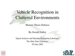
Interactive Perception for Cluttered Environments Bryan Willimon Master’s Thesis Defense
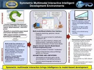
Sense Plan Act Visually-guided Manipulation: Traditional Approach Manipulation-guided Sensing: “Interactive Perception*” Act Sense Plan *D. Katz and O. Brock. Manipulating articulated objects with interactive perception. ICRA 2008
Previous Related Work on Interactive Perception Segmentation through image differencing Learning about prismatic and revolute joints on planar rigid objects D. Katz and O. Brock. Manipulating articulated objects with interactive perception. ICRA 2008 P. Fitzpatrick. First Contact: an active vision approach to segmentation. IROS 2003
Goal of Interactive Perception Pile of Stuff Separate Object Classify Learn
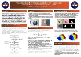
Our Approach • Extraction • Graph-based Segmentation • Stereo Matching • Determining Grasp Point • Classification • Color Histogram Labeling • Skeletonization • Monitoring Object Interaction • Labeling Revolute Joints using Motion
Graph-based Segmentation* • Separates the image into regions based on features of the pixels (e.g., color) • Breaks apart the foreground and background • Classify background as any pixel that shares the same color label as a border pixel. • Subtracts background to leave only foreground *P. Felzenszwalb and D. Huttenlocher. Efficient graph-based image segmentation. IJCV 2004
Stereo Matching* • Uses two different cameras from two slightly different projections to provide a sense of depth • Depth information from foreground only is considered • Foreground image from previous step is used as a mask to erase any background information • Object on top of pile minimizes disturbance *P. Fua. Combining stereo and monocular information to compute dense depth maps that preserve depth discontinuities. IJCAI 1991
Determining Grasp Point • Calculate the maximum chamfer* distance within the white area • Use the outline of the white area as the starting point for the chamfering process • Using chamfer distance instead of centroid handles concave objects *G. Borgefors. Distance transformations in digital images. CVGIP 1986
Color Histogram Labeling* • Use color values (RGB) of the object to create a 3-D histogram • Each histogram is normalized by number of pixels in object to create a probability distribution • Each histogram is then compared to histograms of previous objects for a match using histogram intersection* • White area is found by using same technique as in graph-based segmentation and used as a binary mask to locate object in image *M. Swain and D. Ballard. Color indexing. IJCV 1991
Skeletonization* • Use binary mask from previous step to create a skeleton of the object • Skeleton is a single-pixel wide outline of the area • Prairie-fire analogy Iteration 1 *G. Bertrand. A parallel thinning algorithm for medial surfaces. PRL 1995
Skeletonization* • Use binary mask from previous step to create a skeleton of the object • Skeleton is a single-pixel wide outline of the area • Prairie-fire analogy Iteration 3 *G. Bertrand. A parallel thinning algorithm for medial surfaces. PRL 1995
Skeletonization* • Use binary mask from previous step to create a skeleton of the object • Skeleton is a single-pixel wide outline of the area • Prairie-fire analogy Iteration 5 *G. Bertrand. A parallel thinning algorithm for medial surfaces. PRL 1995
Skeletonization* • Use binary mask from previous step to create a skeleton of the object • Skeleton is a single-pixel wide outline of the area • Prairie-fire analogy Iteration 7 *G. Bertrand. A parallel thinning algorithm for medial surfaces. PRL 1995
Skeletonization* • Use binary mask from previous step to create a skeleton of the object • Skeleton is a single-pixel wide outline of the area • Prairie-fire analogy Iteration 9 *G. Bertrand. A parallel thinning algorithm for medial surfaces. PRL 1995
Skeletonization* • Use binary mask from previous step to create a skeleton of the object • Skeleton is a single-pixel wide outline of the area • Prairie-fire analogy Iteration 10 *G. Bertrand. A parallel thinning algorithm for medial surfaces. PRL 1995
Skeletonization* • Use binary mask from previous step to create a skeleton of the object • Skeleton is a single-pixel wide outline of the area • Prairie-fire analogy Iteration 11 *G. Bertrand. A parallel thinning algorithm for medial surfaces. PRL 1995
Skeletonization* • Use binary mask from previous step to create a skeleton of the object • Skeleton is a single-pixel wide outline of the area • Prairie-fire analogy Iteration 13 *G. Bertrand. A parallel thinning algorithm for medial surfaces. PRL 1995
Skeletonization* • Use binary mask from previous step to create a skeleton of the object • Skeleton is a single-pixel wide outline of the area • Prairie-fire analogy Iteration 15 *G. Bertrand. A parallel thinning algorithm for medial surfaces. PRL 1995
Skeletonization* • Use binary mask from previous step to create a skeleton of the object • Skeleton is a single-pixel wide outline of the area • Prairie-fire analogy Iteration 17 *G. Bertrand. A parallel thinning algorithm for medial surfaces. PRL 1995
Skeletonization* • Use binary mask from previous step to create a skeleton of the object • Skeleton is a single-pixel wide outline of the area • Prairie-fire analogy Iteration 47 *G. Bertrand. A parallel thinning algorithm for medial surfaces. PRL 1995
Monitoring Object Interaction • Use KLT* feature points to track movement of the object as the robot interacts with it • Only concerned with feature points on the object and disregard all other points • Calculate distance between each feature point every flength frames (flength=5) *C. Tomasi and T. Kanade. Detection and tracking of point features. CMU 1991
Monitoring Object Interaction (cont.) • Idea: Like features keep a constant intra-distance, features from different groups have variable intra-distance • Features were separated into groups by measuring the intra-distance amount after flength frames • If the intra-distance between two features changes by less than a threshold, then they are within the same group • Otherwise, they are within different groups • Separate groups relate to separate parts of an object
Labeling Revolute Joints using Motion • For each feature group, create an ellipse that encapsulates all features • Calculate major axis of ellipse using PCA* • End points of major axis correspond to a revolute joint and the endpoint of the extremity *I. Jolliffe. Principal Component Analysis. Springer 1986
Labeling Revolute Joints using Motion (cont.) • Using the skeleton, locate intersection points and end points • Intersection points (Red) = Rigid or Non-rigid joints • End points (Green) = Interaction points • Interaction points are locations that the robot uses to “push” or “poke” the object
Labeling Revolute Joints using Motion (cont.) • Map estimated revolute joint from major axis of ellipse to actual joint in skeleton • In the case of groups with size 1, the revolute joint is labeled to be the closest intersection point • After multiple interactions from the robot, a final skeleton is created with revolute joints labeled (red)
Experiments • Items used for experiments • 3 Logitech Quick-Cam Pro webcams (2 for stereo system and 1 for classifying) • PUMA 500 robotic arm (or EZ gripper) • 2 areas were used and located near each other for easy use of the robotic arm • One was designated as extracted table and the other as classification table
Results Toys on the floor – PUMA 500 Socks and shoes in a hamper – EZ gripper Recycling bin – EZ gripper
Results Toys on the(cont.) floor Final Skeleton used for Classification
Results Toys on the(cont.) floor Final Skeleton used for Classification
Results Toys on the(cont.) floor Final Skeleton used for Classification
Results Toys on the(cont.) floor Final Skeleton used for Classification
Results Toys on the(cont.) floor Classification Experiment 1 2 3 4 5 6 7 8
Results Toys on the(cont.) floor Classification Experiment *Rows = Query image, Columns = Database image
Results Toys on the(cont.) floor Classification Experiment Without use of skeleton
Results Toys on the(cont.) floor Classification Experiment With use of skeleton
Results Recycling(cont.) bin Without use of skeleton
Results Recycling(cont.) bin With use of skeleton
Results Socks and(cont.) Shoes
Results Socks and(cont.) Shoes Only 1 image matched #5, skeleton could not be used
Comparison of Related Work • Comparing objects of the same type to that of similar work* • Pliers from our results compared to shears in their results* Our approach Their approach *D. Katz and O. Brock. Manipulating articulated objects with interactive perception. ICRA 2008
How is our work different? • Our approach handles rigid and non-rigid objects • Most of the previous work only considers planar rigid objects • We gather more information with interaction like a skeleton of the object, color, and movable joints. • Other works only look to segment the object or find revolute and prismatic joints • Our approach works with cluttered environments • Other works only handle a single object instead of working with multiple items piled together
Conclusion • This is a general approach that can be applied to various scenarios using manipulation-guided sensing • The results demonstrated that our approach provided a way to classify rigid and non-rigid objects and label them for sorting and/or pairing purposes • This approach builds on and exceeds previous work in the scope of “interactive perception” • This approach also provides a way to extract items out of a cluttered area one at a time with minimal disturbance • Applications for this project • Service robots handling household chores • Map-making robot learning about the environment while creating a map of the area
Future Work • Create a 3-D environment instead of a 2-D environment • Modify classification area to allow for interactions from more than 2 directions • Improve the gripper of the robot for more robust grasping • Enhance classification algorithm and learning strategy • Use more characteristics to properly label a wider range of objects