Download
1 / 27
270 likes | 377 Views
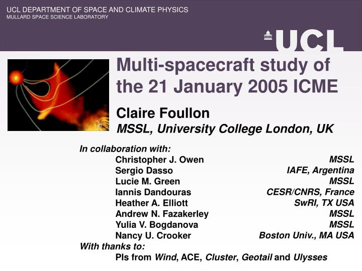
UCL DEPARTMENT OF SPACE AND CLIMATE PHYSICS MULLARD SPACE SCIENCE LABORATORY. Multi-spacecraft study of the 21 January 2005 ICME. Claire Foullon MSSL, University College London, UK. MSSL IAFE, Argentina MSSL CESR/CNRS, France SwRI, TX USA MSSL MSSL Boston Univ., MA USA.

E N D
UCL DEPARTMENT OF SPACE AND CLIMATE PHYSICS MULLARD SPACE SCIENCE LABORATORY Multi-spacecraft study of the 21 January 2005 ICME Claire Foullon MSSL, University College London, UK MSSL IAFE, Argentina MSSL CESR/CNRS, France SwRI, TX USA MSSL MSSL Boston Univ., MA USA In collaboration with: Christopher J. Owen Sergio Dasso Lucie M. Green Iannis Dandouras Heather A. Elliott Andrew N. Fazakerley Yulia V. Bogdanova Nancy U. Crooker With thanks to: PIs from Wind, ACE, Cluster, Geotail and Ulysses
ambient solar wind shock front shocked accelerated particles compressed solar wind ejecta EARTH solar eruption Sun Introduction ICMEs • Shock • Sheath (draping of IMF) • Ejecta Magnetic clouds (MCs): subset of ICMEs • Ejecta: flux rope • Large scale topology from large and coherent rotation of the B-field vector Possibly all ICMEs contain flux ropes but s/c skims the flanks azimuthal field lines, rounding the flux rope axis[Marubashi, 1997]
Intense Solar Energetic Particle (SEP) event of 20 January 2005 Exceptional characteristics • High energy particles: rapid arrival, intensity and energy spectra • High speed of the associated CME What happens further out? • Global geometry of associated ICME? • Specific properties useful for model development?
EARTH Event on 21- 22 Jan 2005 Magnetic cloud-like structure (MCL) Linked to intense Solar Energetic Particle (SEP) event of 20 Jan 2005 Ejecta : 0.5 AU Sheath 18:20 UT26.6 hours21:20 UT MCL : 0.39 AU φGSE(°)θGSE(°)|B| (nT) E W Proton β ACE SA Shock, SB Ejecta Front, CA-CB MCL
W E N ICME in the heliosphere MCL-MC connection: Flux rope of type ENW Ulysses, 5.3AU, 17° south of the ecliptic, 27° from the Sun-Earth line to the west MC Bn/|B|Bt/|B|Br/|B||B| (nT) ULYSSES
W E N ICME in the heliosphere MCL-MC connection: Flux rope of type ENW Ulysses, 5.3AU, 17° south of the ecliptic, 27° from the Sun-Earth line to the west N MC Bn/|B|Bt/|B|Br/|B||B| (nT) E W Looking towards the Sun
Counter-streaming e- EARTH Sideway (E-S) expansion ICME near Earth MCL: Outskirts of a MC in strong expansion Linked to intense Solar Energetic Particle (SEP) event of 20 Jan 2005 Ejecta : 0.5 AU Sheath 18:20 UT26.6 hours21:20 UT MCL : 0.39 AU φGSE(°)θGSE(°)|B| (nT) ACE Leading edge
Near-Earth multi-spacecraft observations North z ACE WIND Upstream near L1 • Wind North-dawn • ACE North-dawn Nearer the Earth • Cluster South-dusk • Geotail North-dawn 4 RE GEOTAIL x 28 RE C3 South Dawn / West 22 RE 19 RE x Earth Sun y Dusk / East
Study of magnetic discontinuities Different scales • Large-scale phenomena: observed by all s/c. • Substructure: differences between s/c. Different methods • Discontinuity normals and velocities from 4-s/c discontinuity analysis on timing difference between C1,C2,C3,C4 • Discontinuity normals only from MVA on single s/c: C3, Wind and ACE
NCDE (He-rich) Magnetic and plasma in-situ observations • Shock SA: ICME shock arrival at ACE– time series shifted with SA. • From SA: Hot pile-up i.e. the sheath • Front SB: discontinuity – well synchronised. • From SB: Colder, denser pile-up, known as Non-Compressive Density Enhancement (NCDE) Sheath Two distinct thermal structures WIND, ACE, C3,Geotail H+ (SWEPAM), ion (HIA/CIS),H+ (SWA/CPI)
196 RE 657 RE Outward IMF Sheath Magnetic discontinuities • SB1-SB2: discontinuity layer (outward and northward IMF), while IMF turns duskward. • SC1-SC2: magnetic layer discontinuity (outward IMF) - observed by ACE, WIND and GEOTAIL- but not C3. - nested time intervals on dawn side - ΔP onGEOTAIL NCDE WIND, ACE, C3,Geotail
Geometry of discontinuities • Agreement between MVA and 4 s/c timing • Quasi-perpendicular upstream B-field with respect to normals z SB2 SB1 SA x Normal to magnetic discontinuity Out of scale (shrinking with time). NCDE Ambient SW Sheath Normals SA, SB along Sun-Earth line but slight differences x Earth Sun y 38.4 RE
Geometry of discontinuities • Agreement between MVA and 4 s/c timing • Quasi-perpendicular upstream B-field with respect to normals z SB2 SB1 SA SC1 SC2 x Normal to magnetic discontinuity IMF Out of scale (shrinking with time). NCDE Ambient SW Sheath Normals SA, SB along Sun-Earth line but slight differences 657 RE 196 RE SC1-SC2 form tilted, curved current sheet Centre of curvature in the north-west x Earth Sun y 38.4 RE
Tilted current sheet draped within overlying cloud canopy Bulk of cloud in N-W sector (primary direction of travel of the fast halo CME) Axis perpendicular to shock and ejecta normals: cloud driving the shock But difference: ejecta front SB due to expansion of cloud (towards E-S), while fast driven shock SA maintains N-W orientation. z SB2 SB1 SA SC1 SC2 x NCDE Ambient SW Sheath 657 RE 196 RE x Earth Sun y 11,860 RE 38.4 RE [Gopalswamy et al. 2005]
NCDE (He-rich) 1. NCDE and helium enhancements SA SB CIS-CODIF Cluster-4 Sheath H+ He2+ H+He2+ O+He+ At Cluster, ‘ion data’ contaminated by He ions. Likely also at ACE (‘proton measurements’).
Ejecta Sheath ACE Cluster-4 (scaled down by 5) Ejecta Sheath Ulysses Large spatial variations in helium enhancements non-homegeneous ‘raisin pudding’ or lumpy distribution [Bame et al. 1979]
NCDE generally associated with low-helium region of the streamer belt[Gosling et al. 1981] Helium enrichment may be attributed to the arrival of flare driver gas[Hirshberg et al. 1972; Bame et al. 1979] Position near streamer belt of the flaring Active Region NOAA 10720 associated with the CME (N14 W67 at time of event). EIT 284 A 2005/01/12 01:06 VSL Solar and Heliospheric Weather model HCS
ULYSSES 2. Speeds and expansion Solar corona 20 Jan 6 UT 2500-3700 km/s[Gopaswalmy et al. 2005; Tylka 2006] Earth At Cluster, 21 Jan, 4 s/c timing analysis Net shock 930 km/s (relative to upstream SW: 374 km/s, MA=5.9, β=1.7) Ejecta 798-837 km/s 1200 km/s ? Transit speeds At ACE, 21 Jan 18:20 UT1200 km/s: slow down AtUlysses, 26 Jan 19 UT 1400 km/s: closer to the primary direction of travel. 1400 km/s ?
ULYSSES 2. Speeds and expansion [Pohjolainen et al. 2007] 1200 km/s IP Scintillation suggests ICME reached 3000 km/s Other possible investigations at Mars (MExpress, MGS) and at Saturn (Cassini, shock front particles). ? Transit speeds At ACE, 21 Jan 18:20 UT1200 km/s: slow down AtUlysses, 26 Jan 19 UT 1400 km/s: closer to the primary direction of travel. 1400 km/s ?
Sideway expansion Ejecta front: overlying canopy of field lines from background corona – connected to flow deflections. Swept up into motion by rising flux rope – primary direction of the cloud. Corroborates differences in acceleration between overlying loops and flux ropes[Rust et al. 2006; Illing & Hundhausen, 1985] [Rust et al. 2006]
3. Flux rope and overlying loops Filament Two-ribbon flare BBSO Halpha 2005/01/19 17:45 Reverse ‘S’ shape [Forbes 2000] TRACE 1600 A 2005/01/20 ~07:00
Two inconsistencies between solar and IP observations: • Ejecta southern flank with inward IMF • Large difference in flux rope orientation N S [Zhang, 2007] • Predominant bipolar fields connected to inward/outward IMF • Filament along curved neutral line (E-W, 10±15°)
Two inconsistencies between solar and IP observations: • Ejecta southern flank with inward IMF • Large difference in flux rope orientation N Helical kink instability Direction of rotation depends on the sign of magnetic helicity (sense of twist in flux rope) Left-handed (-) counter-clockwise Right-handed (+) clockwise S [Zhang, 2007] Negative magnetic helicity • From magnetograms: Hm~ -2 x1043 Mx2[12-18 January, Zhang, 2007] • Reverse ‘S’ shape in EUV ribbons[Titov & Démoulin, 1999] Same left-handed chirality as IP flux rope, consistent with helicity conservation. Flux rope directed towards west counter-clockwise rotation of 80°
Ejective eruption of a kink-unstable flux rope [Török and Kliem, 2005]
Conclusions: main features • Rare identification of a MC on its flank (longitudinal half-extent~67°) • Differences between the shock and ejecta front normals expansion of the cloud on its flank • NCDE caused by enrichment in helium at the ejecta front • Current sheet substructure dragged along between the cloud core (flux rope) and the overlying cloud canopy. • Large (~80°) rotation of the flux rope and overlying arcade (cloud canopy) flux rope being subject to the helical kink instability at the Sun. Foullon et al. 2007, Solar Physics, ‘Sun-Earth Events’ Topical Issue, in press