Download
1 / 24
270 likes | 619 Views
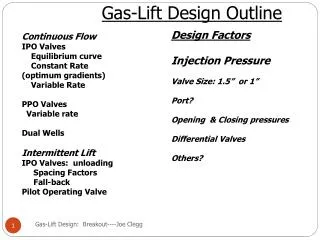
Gas-Lift Optimization and Diagnosis by using Wellflo and Dynalift Simulators By Jayant Sadare & Dr. Faleh T. Al-Saadoon Texas A&M University-Kingsville ASME/API/ISO GAS-LIFT WORKSHOP-2004 . Objectives. Optimization (Wellflo)

E N D
Gas-Lift Optimization and Diagnosis by using Wellflo and Dynalift Simulators By Jayant Sadare & Dr. Faleh T. Al-Saadoon Texas A&M University-Kingsville ASME/API/ISO GAS-LIFT WORKSHOP-2004
Objectives • Optimization (Wellflo) • Advanced Gas Valve Modeling • Diagnosis and Verification (Dynalift) • Implementation
Wellflo Simulator (EPS) USES Nodal Analysis for • Designing • Modeling • Optimizing • Troubleshooting
Input Data Summary • Fluid Properties - Oil Gravity = 35 deg. API - Water Gravity = 1.03 - Gas Gravity = 0.70 - Produced Gas-Oil Ratio = 50.00 scf/STB - Percent Water (%) = 45 • Well-bore Data - Production Casing: 7.000 inch OD × 6.094-inch ID set @ 7100 ft (TVD) - Tubing : 2.875- inch OD × 2.441-inch ID set @6950 ft (TVD) - Well Injection Angle (with vertical) = 0
Contd….. • Reservoir Data Reservoir shut-in pressure = 2400 psig @ 7000 ft Reservoir Temperature = 206 deg F Productivity Index (Straight line) = 2.00 STB/day/psi • Gas-Lift Data Casing Head Pressure = 1450 psig Operating valve Differential Pressure = 150.00 psi Well-head pressure = 102.5 psig Minimum Valve Spacing = 350 ft Injection Gas Rate = 1.000 MMscf/day
Continuous Gas Lift design - Point of Injection • Specify: • - Casing head pressure • - GLR or Qgi • - Pressure drop across valve • Calculates maximum depth of injection and well • performance for gas lift • Sensitivity to CHP, Qgi, GLR
Gas Lift Design - valve spacing for continuousgas lift installations • Specify • - Casing head pressure • - GLR or Qgi - Pressure drop across valve • - Kill fluid gradient • - Maximum depth • - Target operating rate • - Design Margins • Calculates • - depth of unloading and operating valves (IPO/PPO) • - Corresponding tubing/casing pressures & temperatures
Advanced Gas Valve Modeling (AGVM) • True performance of commercial gas lift valves • True operating point of system • Sensitivity to valve type, port size, valve settings • and gas injection parameters • Gas-charged and orifice valve performance
Dynalift Simulator (EPS) Dynamic (Unsteady-State) simulation tool for • Verification • Troubleshooting • Learning
Dynamic Gas-Lift Simulation • This Dynamic simulator uses all the equations used by a steady-state simulator except it adds the dynamic variable (Time). • Uses real correlations to simulate the behavior of gas-lift valves under bottom-hole dynamic conditions. • By controlling the injection conditions, the production parameters are observed to define if the design will work with the selected gas-lift valves. • More realistic performance can be generated • Simulates the system by considering the casing head pressure, gas-injection rate and wellhead pressure at the same time.
Contd…… • This Dynamic simulator is an excellent tool for identifying operational problems with gas-lift installations. • Also best tool to understand the causes for unstable production conditions which not understood with a steady state simulator • It is the best tool for gas lift valves to verify its performance from the unloading operation through all the production life.
Conclusion • Combination of Wellflo and Dynalift is one of the best tool for students to understand gas-lift simulation. • Advanced Gas Valve Modeling (AGVM) is the heart of steady-state simulation. • Do we really need Dynamic Simulation? - Accurately model the well unloading for better design and diagnosis - Minimize unloading time - Accurate valve performance curves - Improve operational procedures