Download
1 / 14
140 likes | 265 Views
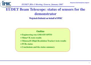
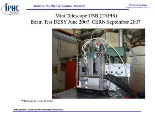
UA9 September 2010 test beam Si telescope hardware status. Mark Raymond – 3/9/10. September test beam telescope layout in128 area. downstream. upstream. trigger scintillators. XY plane. XY planes. UV plane. XY plane. d2. d3. d4. d1. beam. 25 cm. crystal position.

E N D
UA9 September 2010 test beam Si telescope hardware status Mark Raymond – 3/9/10
September test beam telescope layout in128 area downstream upstream trigger scintillators XY plane XY planes UV plane XY plane d2 d3 d4 d1 beam 25 cm crystal position • 5 planes altogether (10 silicon strip sensors) • each plane provides 2 co-ordinates: XY or UV • UV plane = XY plane rotated through 450 (resolves ambiguities for multiple hits / trigger) • d1, d4 as large as possible – maybe ~ 7 m? • d2, d3 as small as possible – d2 depends on goniometer layout • unless use same table for gonio and telescope planes? • table height: surface must be nominally 25 cm below beam height – who will look after? • (note: tables for 138 June test were ~ 3 cm too high)
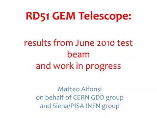
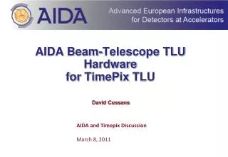
UV plane XY plane sensor planes visible (no window yet) crossover area 4 x 4 cm2 25 cm +/- ~ 4cm
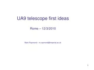
after optical hybrids installed inside the box analogue opto-hybrids fibres finished
cabling, power trigger scintillators XY plane XY planes UV plane XY plane d2 d3 d4 d1 beam 30 analogue readout fibres 5 digital control fibres (clock & trigger) one I2C bus (electrical cable, opto-isolated) I2C hub • to/from counting room • 6 readout fibres per plane => 30 total • 1 control fibre per plane = 5 total • 1 electrical cable to I2C hub in beam area • electrical fanout to each plane • will need some coax cables for trigger,…. • will need 2 mains sockets per plane (LV power, HV supply) • should aim for one multi-socket extension cable per plane (5 total) note: the integrity of these analogue fibres is crucial to the performance of the telescope (the CMS readout system was designed for a one-off, careful installation)
summary & plans • we will provide a total of 5 XY planes for the September test (10 Si planes total) • 2 upstream XY, 2 downstream XY, 1 downstream UV • Geoff will bring hardware to CERN Monday 13th • Oz (Osman Zorba) and Mark (Raymond) will check out hardware in 904 (Prevessin lab) • Tuesday/Weds 14th/15th • => available to help with/advise on any cabling installation • hardware to beam area Thursday 16th – telescope commissioning begins • => would like final version of triggering system there at beginning if possible • table height is only other outstanding issue (I can think of at the moment)
CMS LHC Si strip readout system CMS FED (9U VME) APVMUX APV analog opto-hybrid ~100m lasers inner barrel sensor 96 12 laser driver x15,000 analog optical receivers analogue readout APV25 0.25 mm CMOS FE chip APV outputs analog samples @ 20 Ms/s APVMUX multiplexes 2 APVs onto 1 line @ 40 MHz Laser Driver modulates laser current to drive optical link @ 40 Ms/s / fibre O/E conversion on FED and digitization @ ~ 9 bits (effective)
pipeline 128x192 APSP + 128:1 MUX 128 x preamp/shaper 7.1mm control logic bias gen. FIFO pipe logic CAL 8.1 mm APV25 128 channel chip for AC coupled sensors slow 50 nsec. CR-RC front end amplifier 192 cell deep pipeline (allows up to 4 msec latency + locations to buffer data awaiting readout) peak/deconvolution pipeline readout modes peak mode -> 1 sample -> normal CR-RC pulse shape deconvolution -> 3 consecutive samples combined to give single bunch crossing resolution Decon. Peak noise 270 + 38 e/pF (peak) 430 + 61 e/pF (deconvolution) note: only discrete 25nsec samples of above shapes are available in asynch. test beam choose timing to get close to top of peak mode pulse shape
APV O/P Frame digital header 128 analogue samples APV readout trigger FED VME ~ 10 MB/s readout analog opto-link Slink to CMS DAQ APV provides a timeslice of information from all 128 input channels following external trigger (trigger must be timed-in correctly) no zero-suppression (sparsification) on detector • pedestal, CM subtraction and zero suppression on FED • raw data also available for setup, performance monitoring • and fault diagnosis • can read out raw data at low rate – VME - < 1 kHz • can read out sparsified data faster – VME ~ 10 kHz • (to be verified – some uncertainty here) • Slink faster – 100 kHz – but needs incorporation (and • customized use) of other CMS components • (probably not possible this year) 20 Ms/s readout -> 7 ms
off-detector FED functionality • opto-electric conversion • 10 bit 40 MHz digitization • pedestal and CM subtraction • hit finding (sparsification) • formatting and transmission of data • up to higher DAQ level • check of APV synchronization • all tracker synchronous, so all pipeline • addresses of all APVs should be • the same • FED checks received APV pipe address • matches with expected value • (APV logic emulated at trigger level) 9U VME
UA9 telescope readout system APVMUX CMS FED (9U VME) APV analog opto-hybrid ~100m lasers inner barrel sensor 96 12 laser driver PA make use of most components but different sensors – no PA readout fibre ribbons plug straight into FED
HV, LV I2C, RST Ck/T1 telescope sensor module ceramic piece (same thickness as hybrid) ceramic hybrid D0 sensor 60 um pitch (+ intermediate strip) ~ 8 um resolution AOH Al support plate with cutout beneath sensor peltier heatsink fan
HV, LV I2C, RST Ck/T1 HV, LV I2C, RST Ck/T1 sensor AOH XY plane sensor AOH crossover area ~ 4 x 4 cm2 interface circuitry optical fibre adaptors power supply conditioning peltier cooling control ….. power slow control fast control (40 MHz ck, trigger) fibre ribbon readout