Download
1 / 10
100 likes | 103 Views
This article will include these subject.<br>What does WDM stand for?<br>The basic structure of WDM system<br>Advantages of WDM technology<br>What does Mux and Demux stand for?<br>The difference between WDM and optical splitter<br>The indicators that affect the WDM devices<br>How t

E N D
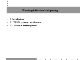
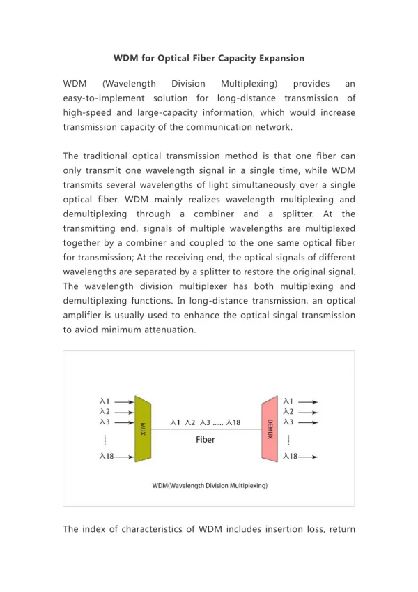
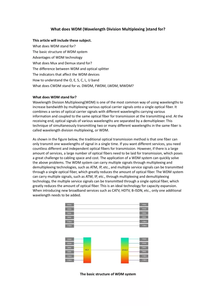
What does WDM (Wavelength Division Multiplexing )stand for? This article will include these subject. What does WDM stand for? The basic structure of WDM system Advantages of WDM technology What does Mux and Demux stand for? The difference between WDM and optical splitter The indicators that affect the WDM devices How to understand the O, E, S, C, L, U band What does CWDM stand for vs. DWDM, FWDM, LWDM, MWDM? What does WDM stand for? Wavelength Division Multiplexing(WDM) is one of the most common way of using wavelengths to increase bandwidth by multiplexing various optical carrier signals onto a single optical fiber. It combines a series of optical carrier signals with different wavelengths carrying various information and coupled to the same optical fiber for transmission at the transmitting end. At the receiving end, optical signals of various wavelengths are separated by a demultiplexer. This technique of simultaneously transmitting two or many different wavelengths in the same fiber is called wavelength division multiplexing, or WDM. As shown in the figure below, the traditional optical transmission method is that one fiber can only transmit one wavelengths of signal in a single time. If you want different services, you need countless different and independent optical fibers for transmission. However, if there is a large amount of services, a large number of optical fibers need to be laid for transmission, which poses a great challenge to cabling space and cost. The application of a WDM system can quickly solve the above problems. The WDM system can carry multiple signals through multiplexing and demultiplexing technologies, such as ATM, IP, etc., and multiple service signals can be transmitted through a single optical fiber, which greatly reduces the amount of optical fiber. The WDM system can carry multiple signals, such as ATM, IP, etc., through multiplexing and demultiplexing technology, the multiple service signals can be transmitted through a single optical fiber, which greatly reduces the amount of optical fiber. This is an ideal technology for capacity expansion. When introducing new broadband services such as CATV, HDTV, B-ISDN, etc., only one additional wavelength needs to be added. The basic structure of WDM system
The basic structure of the WDM system is mainly divided into two modes: dual-fiber unidirectional transmission and single-fiber bidirectional transmission. Unidirectional WDM is the transmission of all optical channels on a fiber propagating simultaneously in the same direction. Different wavelengths carry different optical signals, which are combined at the transmitting end for transmission through an optical fiber, and demultiplexed at the receiving end to complete multiple paths. In the opposite direction, a second optical fiber is needed. The transmission in the two directions is completed by two optical fibers respectively. Bidirectional WDM is the transmission of optical channels on a fiber propagating simultaneously in both directions, and the wavelengths used are separated from each other to achieve full-duplex communication between the two parties. Unidirectional WDM Bidirectional WDM The general WDM system is mainly composed of five parts: network management system, optical transmitter, optical relay amplifier, optical receiver, and optical monitoring channel.
The overall structure of the WDM system The simple WDM system mainly includes transceivers, WDM wavelength division multiplexers, patch cord, and dark fiber components. WDM system In the entire WDM system, the multiplexer and demultiplexer are key components in the WDM technology, and their performance is decisive for the transmission quality of the system. Advantages of WDM technology Large capacity An important feature of WDM is that it can make full use of the bandwidth resources of the optical fiber and increase the data transmission capacity without changing the existing network infrastructure, so that the transmission capacity of an optical fiber is multiple times that of a single wavelength. For example, the DWDM system can support up to 192 wavelengths in a pair of optical fibers, and the transmission capacity of each wavelength is as high as 100Gbit/s ~ 400Gbit/s and one Terabit/s. Good compatibility WDM has good compatibility with different signals. When transmitting signals with different properties such as image, data and voice, each wavelength is independent from each other and does not interfere with each other to ensure the transparency of transmission.
Flexibility, economy and reliability WDM technology allows new channels to be connected as needed without changing the existing network, which makes upgrades easier. When upgrading and expanding the network, there is no need to renovate the optical cable line, and new businesses can be opened or superimposed by adding wavelengths. Optical fibers and 3R regenerators can be saved during large-capacity long-distance transmission, and the transmission cost is significantly reduced. Wavelength routing WDM technology is one of the key technologies for realizing all-optical networks. In the all-optical network that is expected to be realized in the future, by changing and adjusting the wavelength of the optical signal on the optical path, the up/down and cross-connection of various telecommunication services can be realized. What does Mux and Demux stand for? MUX The main function of the combiner MUX is to combine multiple signal wavelengths into one fiber for transmission. At the transmitting end, the N optical transmitters operate on N different wavelengths respectively, and the N wavelengths are separated by appropriate intervals, which are respectively recorded as λ 1, λ 2, ... λ n. A multiplexer combines these optical wavelengths into a single-mode fiber. Since optical carrier signals of different wavelengths can be regarded as independent of each other (regardless of fiber nonlinearity), multiplexing transmission of multiple optical signals can be realized in one optical fiber. Through multiplexing, communication carriers can avoid maintaining multiple lines and effectively save operating costs. DEMUX The main function of DEMUX is to separate the multiple wavelength signals transmitted in one fiber. In the receiving part, the optical carrier signals of different wavelengths are separated by a Demux and further processed by the optical receiver to restore the original signal. A multiplexer (Demux) is a device that reverses the processing of a multiplexer. In principle, the device is reciprocal (two-way reversible), that is, as long as the output and input of the demultiplexer are used in reverse, it is a multiplexer. The difference between WDM and optical splitter Many people cannot understand the difference between wavelength division multiplexing and optical splitters. In short, WDM separates and transmits light of multiple wavelengths in the line. Of course, it can also transmit light of multiple wavelengths together. The optical splitter divides the light of one wavelength into multiple beams according to the purpose. The power of the light depends on the specifications of the splitter used. The most important difference between the two is that the former can compositely transmit optical signals of various service wavelengths, while the latter can only transmit light of one wavelength to split light according to a specific splitting ratio.
The indicators that affect the WDM devices Working band Working bands of the multiplexer/demultiplexer. For example, there is three bands of 1550 wavelength: S-band (short-wavelength 1460~1528nm), C band (conventional band 1530~1565nm), L band (long-wavelength band 1565~1625nm). Number of channels & channel spacing The number of channels is the number of channels the device has to send information. This number can range from 4 to 160 with design enhancements adding more channels. The normal channels are 4, 8, 16, 32, 40, 48, etc. Channel spacing is the center-to-center difference in frequency between neighboring channels. It can be used to prevent inter-channel interference. Insertion loss Insertion loss is the attenuation caused by the insertion of wavelength division multiplexers (WDM) in an optical transmission system. The attenuation effect of wavelength division multiplexer directly affects the transmission distance of the system. In general, the lower the insertion loss, the less the signal attenuation. Isolation Isolation refers to the degree of isolation between individual channel signals. High isolation values can effectively prevent crosstalk between signals and cause distortion of the transmission signal. Polarization dependent loss( (PDL) ) Polarization-dependent loss is the maximum deviation in insertion loss across all input polarization states. In addition to the above, there are of course other performance parameters that affect the multiplexing/demultiplexing devices, such as operating temperature, bandwidth, etc. Generally, a multiplexer and a demultiplexer are combined into a single device allowing the device to process both incoming and outgoing signals. Or a single output of a multiplexer can be connected
through a single channel to a single input of a demultiplexer. But mostly is the combined and complex devices for both directions transmission. How to understand the O, E, S, C, L, U band What is O band? The O band is the original band with wavelength from 1260 to 1360nm. The O-band is the first wavelength band used in optical communications in history, and the signal distortion (due to dispersion) is minimal. What is E band? The E-band (extended wavelength band: 1360-1460 nm) is the least common of these bands. The E-band is mainly used for the expansion of the O-band, but it is rarely used, mainly because many existing optical cables show high attenuation in the E-band and the manufacturing process is very energy-intensive, so the use in optical communication is limited. What is S band? The optical fiber loss in the S-band (Short-wavelength Band, 1460-1530 nm) is lower than the loss in the O-band. The S-band is used as many PON (passive optical network) systems. What is C band? The C-band (Conventional Band) ranges from 1530 nm to 1565nm and represents the conventional band. Optical fiber shows the lowest loss in the C-band and occupies a large advantage in long-distance transmission systems. It is usually used in many metropolitan areas combined with WDM, long-distance, ultra-long-distance and submarine optical transmission systems and EDFA technology. As the transmission distance becomes longer, and fiber optic amplifiers are used instead of optical-to-electronic-to-optical repeaters, the C-band becomes more and more important. With the advent of DWDM (Dense Wavelength Division Multiplexing) that allows multiple signals to share a single fiber, the use of the C-band has been expanded. What is L band?
The L-band (Long-wavelength Band, 1565-1625nm) is the second lowest-loss wavelength band, and is often used when the C-band is insufficient to meet the bandwidth requirements. With the wide availability of b-doped fiber amplifiers (EDFAs), DWDM systems have expanded upward to the L-band, and were initially used to expand the capacity of terrestrial DWDM optical networks. Now, it has been introduced to submarine cable operators to do the same thing-to expand the total capacity of submarine cables. Due to its low transmission attenuation loss, C-band and L-band is usually selected to use in the DWDM system. Except for the O-band and L-band, there are two other bands, 850nm band and the U band (ultra-long band: 1625-1675 nm). The 850nm band is the main wavelength of the multimode optical fiber communication system, which combines VCSEL (Vertical Cavity Surface Emitting Laser). The U frequency band is mainly used for network monitoring. Band Description Wavelength range Bandwidth O band original 1260-1360nm 100 E band extended 1360-1460nm 100 S band Short wavelength 1460-1530nm 65 C band conventional 1530-1565nm 40 L band Long wavelength 1565-1625nm 60 U band Ultralong wavelength 1625-1675nm 50 WDM technology can be divided into WDM, CWDM, DWDM according to different wavelength modes. The wavelength range stipulated by ITU for CWDM (ITU-T G.694.2) is 1271 to 1611nm, but considering the attenuation of the 1270-1470nm band in the application, the band of 1470~1610nm is usually used. The channel space of DWDM is more closeness, so choose the C-band (1530 nm-1565 nm) and L-band (1570 nm-1610 nm) transmission windows. Ordinary WDM generally uses 1310 and 1550nm wavelengths. What does CWDM stand for vs. DWDM, FWDM, LWDM, MWDM? WDM solutions include coarse wavelength division multiplexing (CWDM), dense wavelength division multiplexing (DWDM), medium wavelength division multiplexing (MWDM), and Lan wavelength division multiplexing (LWDM). CWDM (Coarse Wavelength Division Multiplexing) The CWDM wavelength set consists of a series of 18 wavelengths spaced 20nm apart, from 1270nm to 1610nm. The biggest advantage of CWDM systems is the low cost, and the component cost is mainly reflected in filters and lasers. The wide wavelength spacing of 20 nm also gives CWDM the advantage of low specification of the laser and simplified structure of the optical multiplexer/demultiplexer. The structure is simplified, the yield is improved, so the cost is reduced.
DWDM( DWDM can carry 40, 80 or up to 160 wavelengths with a narrower spacing of 1.6/0.8/0.4nm (200/100/50GHz). The DWDM module further increases the system bandwidth and capacity by using tightly spaced wavelengths to carry more signals on the same fiber. DWDM is mainly due to the high cost of laser diodes and the cooling laser technology used to maintain wavelength stability. Compared with CWDM, DWDM with tighter wavelength spacing can carry 8 to 160 wavelengths on an optical fiber, which is more suitable for long-distance transmission. With the help of EDFA, DWDM system can work within thousands of kilometers. (Dense Wavelength Division Multiplexer) ) FWDM( The filter type WDM is based on mature membrane filter technology. Filter-type WDM can combine or separate light of different wavelengths in a wide wavelength range, and are widely used in erbium-doped optical amplifiers, Raman amplifiers and WDM optical fiber networks. MWDM( (Medium Wavelength Division Multiplexing) MWDM is proposed based on mature CWDM technology. CWDM has 18 wavelengths (1271~1611nm), but due to the relatively large attenuation of the 1270~1470nm band and cost considerations, usually only 6 wavelengths (1271nm, 1291nm, 1311nm, 1351nm, 1371nm) are used. MWDM reuses the first 6 wavelengths of CWDM, compresses the 20nm wavelength interval of CWDM to 7nm, and uses Thermal Electronic Cooler (TEC) temperature control technology to expand 1 wave into 2 waves. In this way, an increase in capacity can be achieved (Filter Wavelength Division Multiplexing) ) )
while further saving optical fibers. MWDM is based on the 6 wavelengths of CWDM, shifted by 3.5nm left and right to expand to 12 waves (1267.5, 1274.5, 1287.5, 1294.5, 1307.5, 1314.5, 1327.5, 1334.5, 1347.5, 1354.5, 1367.5, 1374.5nm). LWDM( LWDM is based on the Ethernet channel wavelength division multiplexing Lan-WDM technology, also known as dense wavelength division multiplexing. Its channel interval is 200~800GHz, this range is between DWDM (100GHz, 50GHz) and CWDM (about 3THz). LWDM uses 12 wavelengths in the O-band range from 1269nm to 1332nm, with a wavelength interval of 4nm (Wavelengths including 1269.23, 1273.54, 1277.89, 1282.26, 1286.66, 1291.1, 1295.56, 1300.05, 1304.58, 1309.14, 1313.73 , 1318.35nm). The characteristic of LWDM working wavelength is that it is located near zero dispersion, with small dispersion and good stability. At the same time, LWDM can support 12-wave 25G to increase the capacity and save fiber. (Lan Wavelength Division Multiplexing) )
MWDM LWDM CWDM DWDM Channel Spacing 20nm 1.6, 0.8, 0.4 nm 7nm 4nm 1269.23、 1273.54、 1277.89、 1282.26、 1286.66、1291.1、 1295.56、 1300.05、 1304.58、 1309.14、 1313.73、 1318.35nm 12 channels 1267.5、 1274.5、 1287.5、 1294.5、 1307.5、 1314.5、 1327.5、 1334.5、 1347.5、 1354.5、 1367.5、 1374.5nm 1270~1610nm O/E/S+C+L band 1525~1565nm(C band) 1570~1610nm(L band) Wavelengths 12 channels Number of channels Up to 18 channels 40,80, up to 160 wavelength for short distance < 160km longer haul transmit over 1,000 kilometers can be achieved Transmission Distance Cost cost-effective more expensive Suitable for long distance, large capacity long-distance trunk networks, or ultra large capacity man core node, or large-capacity metropolitan area network core nodes, telecom 5G, metropolitan area networks, backbone networks, data centers, etc. Man access layer, telecommunica tions, enterprise network, campus network, etc. Application HYC can provide customers with a one-stop optical network device and low-cost optical communication products, supplying a range of WDM products. HYC Co.,Ltd(HYC)is a national Hi-tech optoelectronics company engaged in R&D, manufacture and marketing of fiber optical products. Providing professional product and service for fiber connectivity,WDM, PLC splitter and high density datacom cabling. HYC products and solutions widely applied in 4G/5G, Data Center and Cloud Computing industry etc. http://www.hyc-system.com sales@hyc-system.com