Download
1 / 40
420 likes | 465 Views
PH is a unit of measure which describes the degree of acidity or alkalinity of a solution. Acidity is defined as the concentration of hydrogen ions [H ] in solution and alkalinity as the concentration of hydroxyl ions [OH- ] in solution. Visit https://bit.ly/3chZIk6 for more info.

E N D
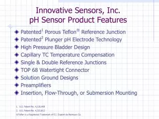
TECHNICAL GUIDE pH SENSOR um-600-sensor-r6 642 pH Sensor 617 High Pressure Ball Valve Retractable 614 True-Union Sensor 615 Pure Water pH Sensor 607 Ball Valve Retractable Cartridge pH Sensor
CONTENTS IC Controls CONTENTS um-600-sensor-r6 CONTENTS.........................................................................................................................2 pH MEASUREMENT.........................................................................................................3 WHAT IS pH?.................................................................................................................3 pH Measurement Techniques..........................................................................................3 pH Sensing Electrode......................................................................................................4 The Reference Electrode.................................................................................................6 pH Concerns In Industry.................................................................................................8 INSTALLATION..............................................................................................................15 Selecting the Location...................................................................................................15 Analyzer Location.........................................................................................................15 pH Sensor Mounting.....................................................................................................15 Sensor Wiring................................................................................................................19 Instrument Shop Tests...................................................................................................20 Preparation for Use........................................................................................................21 pH CALIBRATION...........................................................................................................22 Selecting a pH Buffer....................................................................................................22 Electrode Life................................................................................................................23 Standardizing ─ Single-Buffer Calibration...................................................................24 Calibrating ─ Two-Buffer Calibration..........................................................................25 Grab Sample ─ At Process Calibration.........................................................................26 INSERTING/REMOVING pH SENSORS.......................................................................28 Preparation for Use........................................................................................................28 Inserting pH Sensors.....................................................................................................28 pH Sensor Removal.......................................................................................................30 Removal 605-21 & 606-21 BV Sensor.........................................................................31 SENSOR MAINTENANCE..............................................................................................32 Sensor Storage...............................................................................................................32 Monthly Maintenance...................................................................................................32 Yearly Maintenance......................................................................................................32 Sensor Cleaning............................................................................................................32 Mechanical Cleaning of Sensor.....................................................................................33 pH SENSOR TROUBLESHOOTING..............................................................................35 Troubleshooting Tips for pH.........................................................................................36 GLOSSARY......................................................................................................................38 DRAWINGS......................................................................................................................39 D5160327: Generic pH Sensor Wiring Diagram..........................................................39 D4850015: pH Interface................................................................................................40 © Copyright 2018 IC Controls Ltd. All rights reserved. Page 2 www.iccontrols.com um-600-sensor-r6
IC Controls pH MEASUREMENT pH MEASUREMENT concentration of hydrogen ions [H+] in solution and alkalinity as the concentration of hydroxyl ions [OH-] in solution. The actual theoretical definition of pH is - log10aH+. However, since the activity coefficient (a) for hydrogen (H+) is 1, the practical definition for pH can then be defined as -log10[H+]. Refer to table 1 for a chart showing the relationship between pH and the hydrogen ion concentration. WHAT IS pH? pH is a short form for the Power (p) of Hydrogen (H). pH is defined as the negative log of the hydrogen ion activity, aH+ or the effective hydrogen ion concentration. Mathematical Definition 1 aH+1=−log10aH 1 [H+1]=−log10[H+1] Descriptive Definition pH is a unit of measure which describes the degree of acidity or alkalinity of a solution. Acidity is defined as the pH Measurement Techniques +1 pH=log10 (Theoretical) There are two ways of measuringpH. The first is a Colorimetric Methodwhich uses color indicators to indicate the pH of the sample. There are limitations to this measurement technique; for instance, visual measurement by an operator is subject to variation. As well, this technique is done by grab sample which is not suitable for continuous on-line measurement. A more effective way tomeasure pH in an industrial setting is via the potentiometric method of pH analysis. The potentiometric method allows continuous on-line measurement and is not subject to operator bias. Potentiometric analysis consists of four parts; (10-10) pH=log10 (Practical) pH Hydrogen Ion (H+) Moles per Liter Hydroxyl Ion (OH-) Moles per Liter (100) 0.00000000000001 (10-14) 0 1 (10-1) (10-13) 1 0.1 0.0000000000001 (10-2) (10-12) 2 0.01 0.000000000001 (10-3) (10-11) 3 0.001 0.00000000001 (10-4) 4 0.0001 0.0000000001 1) sample (10-5) (10-9) 5 0.00001 0.000000001 2) pH sensing electrode (10-6) (10-8) 6 0.000001 0.00000001 (10-7) (10-7) 7 0.0000001 0.0000001 3) reference electrode (10-8) (10-6) 8 0.00000001 0.000001 4) signal amplifier/readout (10-9) (10-5) 9 0.000000001 0.00001 When properly combined, the result is accurate, representative pH readings. 10 (10-10) (10-4) 0.0000000001 0.0001 11 (10-11) (10-3) 0.000000000001 0.001 12 (10-12) 0.0000000000001 (10-2) 0.01 13 (10-13) 0.00000000000001 (10-1) 0.1 14 (10-14) 0.000000000000001 (100) 1 Table 1: Relationship between pH and hydrogen ion concentration um-600-sensor-r6 www.iccontrols.com Page 3
pH MEASUREMENT IC Controls The glass electrode is primarily composed of alkali silicates which arecomprised of sodium, potassium, lithium, silicate, oxygen and hydrogen. All of these components are combined to form a hydrogen ion specific sensing glass; the amount of each constituent in the glass determining its pH sensing properties. pH Sensing Electrode The pH sensing electrode acts as one half of a battery whose potential varies with the hydrogen ion concentration in solution. The standard glass electrode is commonly used in industrial applications because of its ruggedness and versatility. There are other solid state electrodes such as the antimony electrode which is a sensing element made of antimony hydroxide and is used in applications such as high fluoride where glass is dissolved. The Glass Electrode Since the glass electrode is still the industry standard for sensing electrodes, it will be the only sensing electrode discussed. The glass electrode generally consists of four major components; When the glass is put into solution, it undergoes a chemical reaction which forms of a leached layer. The leached layer is the area at the surface of the glass where an ion exchange reaction occurs. In this surface layer, hydrogen ions migrate in and replace other positively charged ions such as sodium or potassium. This causes a silica-oxygen-hydrogen bond to be set up which is essential for sensing hydrogen ion in solution. The pH glass electrode actually works on a two reference electrode basis; a reference inside the glass and a reference that is in contact with the externals of the glass. pH measurement requires measurement of the potential difference in the pH electrode system. The formation of a leached layer actually occurs on both sides of the glass membrane. The difference in potential between the two layers is called the phase boundary potential and is the potential difference that gives the pH signal. 1) glass membrane 2) internal buffer solution 3) reference wire 4) glass stem In the pH glass there must also be a charge transport mechanism so that a millivolt potential will be seen. In between the two leached layers there remains a glass membrane layer that does not undergo the ion exchange that occurs at the surface. In this membrane layer, potassium and sodium, major constituents of the glass, act as the charge carriers. Illustration 1: Glass pH electrode For best results, a symmetrical cell is set up on both sides of the glass membrane. To How Glass Electrodes Work Page 4 www.iccontrols.com um-600-sensor-r6
IC Controls pH MEASUREMENT set up the symmetrical cell, the internal fill solution in the glass and the reference fill solution are similar in their makeup. The symmetry is important so that the temperature curves for the two solutions are as close as possible and minimize the temperature effect. purposes, the internal buffer is made of potassium chloride (KCl) solution which is the same as the reference solution. more conductive the glass is, the quicker the transfer of potential difference across the membrane. Thicker, ruggedized styles of glass are slower to respond in ambient conditions than general purpose electrodes because it takes longer to transfer the charge and set up the difference between the leached layer potentials. For symmetry The conductivity of the glass, which is the reciprocal of resistance, is highly temperature dependent, as seen in the following equation; where k is the conductivity and A and B are constants: −logk=A+B T Styles of Glass Electrodes The basic premise behind glass electrodes is to have the reference and the hydrogen ion sensitive glass membrane in contact with the solution being monitored. The glass membrane itself is not limited to any configuration or shape; its only requirement is contact with the solution. Therefore, different styles of glass electrodes have evolved to maximize pH sensing ability and extend longevity in some of the more harsh applications. Refer to illustration 2 for examples of various glass styles. From this equation, it is evident that as the temperature increases the conductivity of the glass also increases. This explains why thick glass, which is somewhat sluggish at ambient temperatures, will be very responsive when the temperature of the sample is increased. Illustration 3 is a graph that shows this relationship between temperature and the conductivity of the glass for a standard glass membrane. Illustration 2: A) Dome B) Spherical C) Flat Temperature Effect on Glass As the charge transfer is one of the key factors in determining pH, the conductivity of the internal layer of the glass is a factor in the responsiveness of the electrode. The Illustration 3: Temperature vs. pH glass resistance Because of the temperature effect on the impedance of the glass, a thinner glass with a low impedance is used in ambient conditions and a thicker more rugged glass um-600-sensor-r6 www.iccontrols.com Page 5
pH MEASUREMENT IC Controls with a higher initial impedance is used for high temperature applications. friendly than the Ag/AgCl reference. The Ag/AgCl reference has a number of advantages for use in the industrial pH market. First, the temperature stability of this reference is good in applications ranging up to 105 °C (220 °F). However, when stabilizers are added to the reference, accurate pH measurements can be taken to temperatures in excess of 125 °C (260 °F). With the stability of this reference and the relative ease of manufacture into a combination electrode, the Ag/AgCl reference has become IC Controls' standard. Therefore, when selecting a glass electrode for industrial pH systems, a number of different factors must be considered to maximize response and longevity of the probe in specific applications. The Reference Electrode The reference electrode acts as the other half of the battery in the pH electrode. The difference in potential between the two sides of the pH glass measures the varying potential difference in the solutions due to pH. Where the reference is constant, it gives the glass a reference point to use for the glass electrode to distinguish that pH relates to the process pH potentials. As mentioned in the glass section, the best results for an electrode occur when the two sides are symmetrical. Thus, a reference cell is normally comprised of a silver (Ag) wire with the tip of the wire covered in silver chloride (AgCl). This Ag/AgCl wire is submersed in a saturated KCl solution which is separated from the process by a porous junction. A diagram of a typical combination electrode with an Ag/AgCl reference can be seen in illustration 4. Illustration 4: Combo electrode with Ag/AgCl reference Reference Junction Impact The silver/silver chloride reference has a porous junction between the KCl reference solution and the process. This porous junction acts as a barrier to keep the reference internals and the process from readily mixing and contaminating the reference which would render the reference useless. Like the glass electrode, there are also different types of reference electrodes that can be utilized in any given pH measurement. The two common references are the calomel electrode and the silver/silver chloridereference. The calomel electrode is not used in industrial applications for two reasons. First, the electrode tends to breakdown when the temperature exceeds 80 °C or 175 °F. As well, the calomel electrode is partially comprised of mercury which is known to be a health hazard thus making it less user Like the glass membrane, the junction can cause a noticeable potential difference in the electrode. The difference in the magnitude of this potential is small in comparison to the glass but significant Page 6 www.iccontrols.com um-600-sensor-r6
IC Controls pH MEASUREMENT enough that choosing the proper junction can have an effect on the pH measurement. In considering which junction is used for an electrode, the chemical compatibility of the reference junction material with the process must also be considered. Ceramic Junctions In the industrial pH electrode there are basically three styles of reference junctions that can be selected; ceramic, wood or porous plastic, depending on the process application. The first is the ceramic junction which is very useful in ultra high accuracy types of pH measurements due to its low junction potential. However, there are some limitations with using this junction. The junction usually has very little surface area in contact with the process making it prone to clogging, especially in dirty or oily industrial applications. As well, because of the very brittle nature of ceramic, it is less shock resistant in applications where the electrode comes in contact with small rocks or pieces of debris on a regular basis. use in applications where coating from the process can occur. IC Controls' wood junctions are normally manufactured with a larger surface area allowing for better contact with the process which is essential in the dirtier applications that try to clog the reference junction. The limitation of wood occurs in high temperature and high pH environments. Porous Plastic For high temperature and high pH applications, a porous plastic junction is used because it is chemically resistant and is not affected by temperature in the readable temperature range of pH. Like wood, IC Controls' porous plastics are manufactured with large surface areas so that good solution contact is maintained. If an application is running over 50 °C (122 ° F) or above pH 8 continuously, a porous plastic junction will provide best results. For these reasons, the ceramic junction is primarily used in the laboratory for grab sample purposes where high accuracy is required and the electrode will not be subject to the rigors of the process. Wood Junctions Another type of junction that can be used with the pH electrode is the wood junction. Wood, by nature, allows good transport of liquid through its fiber and resists coating from most substances. These two features make the wood junction exceptional for um-600-sensor-r6 www.iccontrols.com Page 7
pH MEASUREMENT IC Controls analyzers. The closer the slope is to 100%, the greater the efficiency and thus the performance of the electrode. Heat Effect on Slope At 25 °C the slope of a 100% efficient probe is 59.16 mV per pH unit with 0 mV starting at pH 7. However, as the temperature changes, so does the mV per pH unit as seen in illustration 5. In fact, the slope changes 0.1984 mV/°C. This relationship is important in determining pH because if it is not used, the reading could be off by a significant amount. pH Concerns In Industry Industrial pH applications exhibit a number of different problems that are common and cause difficulties when trying to measure pH. Below is a list of some of the most common pH measurement dilemmas and how to approach them to obtain optimal results. Slope and Offset The slope and offset are measures of probe efficiency and how close to theoretically perfect the probe is. When a calibration is performed, the first step is to use pH 7 buffer to calculate the mV offset of the electrode from theoretically perfect 0 mV. A larger mV offset is farther from a theoretically perfect electrode. pH 7 buffer is used because it simulates 0 mV thus making it the best standard to calculate the offset from this 0 mV reference point. The next step in the calibration is to use a second buffer, usually pH 4 or pH 10 buffer; either of these buffers gives a large enough mV differential that a good slope can be calculated. When calculating the slope of the electrode a good separation between the buffers is needed so that an accurate span between two points is calculated. As well, when choosing which buffers to use in calibration, it is best to select buffers that fall on both sides of the normal operating pH. By using these two buffers, the slope calculation will encompass the normal pH, thus giving the most accurate pH measurement. At 25 °C (77 °F), the slope is 59.16 mV per pH unit and the slope is measured as a percentage of this millivoltage. When performing the two point calibration, a percent value will be given in microprocessor based pH Illustration 5: Temperature vs. mV/pH unit For example, pH is being monitored in a process at pH 4 and 60 °C. The output from the probe will be 198 mV according to the temperature to mV relationship. If the analyzer does not use temperature compensation, it will see 198 mV and assume this reading is taken at 25 °C. At 25 °C, 198 mV is calculated by the pH meter to have a pH value of 3.64 which is a third of a pH unit lower than 4.0 pH. Hence, it is vital to ensure temperature compensation is used and working properly in conjunction with the pH probe so that accurate pH readings are given by the analyzer. Page 8 www.iccontrols.com um-600-sensor-r6
IC Controls pH MEASUREMENT Caustic Ion Error Another problem with pH electrodes occurs at the high end of the pH scale when the concentration of hydrogen ions is low. In fact, high pH causes two problems. First, there is a high concentration of hydroxide (OH-) ions coupled with extremely low hydrogen ions which will dehydrate the glass making it very sluggish in responding to pH changes. Secondly, and more importantly, a caustic (sodium) ion error will occur if the proper glass is not used. As the pH value increases, the concentration of hydrogen ion decreases. At the same time, the concentration of sodium ion will increase. Sodium is very close to hydrogen in its chemical structure and, as a result, when the concentration of hydrogen ion decreases the glass will start to recognize sodium as hydrogen giving a false, low pH reading. By using high pH glass, the sodium ion error will be negated as seen in illustration 6. Illustration 6 graphically depicts the significant effect using the proper glass can have on the accuracy of a pH reading. Another benefit of high pH glass is its resistance to caustic etching. Thus, using high pH glass will result in improved performance as well as increased sensor longevity. Coating of the Glass Various applications contain constituents that will coat the glass, such as calcium carbonate which is present in systems where lime addition is used for effluent neutralization. Coating of the glass results in poor contact between the glass itself and the process. Good contact by the electrode is essential for accurate speedy response in the process. Thus, to keep the glass clean and responsive, there are a couple of procedures that can be used to help. The first is to insert the electrode with the flutes at 75 degrees to flow, as indicated in illustration 7. By inserting the probe at this angle, a vortex will be created around the glass. The vortex will increase the velocity of the process around the glass and reference which will hasten electrode response time and also keep the reference cleaner. Also, by turning the flutes to 75 degrees, the process does not directly hit the glass which will slow down the coating action. Illustration 7: Electrode flute angles When the probe shows evidence of coating, a good cleaning procedure should be used to restore the electrode back to 100%. In the past, a hydrochloric acid solution was used to remove scale from the tip of the electrode. Although this has been somewhat effective, a gentle scale remover will better clean the electrode. If the pH response becomes sluggish and the Illustration 6: High pH effect um-600-sensor-r6 www.iccontrols.com Page 9
pH MEASUREMENT IC Controls slope of the probe starts to get too low, an electrode renew solution can be used. The electrode renew solution will skim off a micro-layer of the coated glass, thus exposing a new glass surface which will exhibit better pH response. Ground Loops One of the more difficult problems to analyze in a pH loop is a ground loop which does not necessarily exhibit any visual signs. Unlike scaling or even caustic ion error, which is specifically looked for at high pH values, a ground loop can occur at any pH under many different conditions. Fortunately, there are certain indicators that point to a ground loop problem. the reference electrode - some constituents migrate into the reference and attack the Ag/AgCl reference wire causing the wire to deteriorate over time. The reference offset is a gage of the reference electrode's level of deterioration. As the offset from 0 mV increases, the reference is becoming more contaminated. Within an offset of 1.3 pH units, the electrode is still deemed to be adequate for use. Between 1.3 pH and 4 pH units, the electrode may still be within a usable range but has deteriorated significantly. When the offset reaches 4 pH units or 240 mV, the reference has been contaminated to the point where it can no longer be relied upon for use in the process. There are two major contaminants in the industrial market, sulfide (S2-) and cyanide (CN-). Sulfide is commonly found in Kraft pulp and paper mills. All of the different liquors analyzed in Kraft processes have a high sulfide content, therefore, the pulp stock will have a significant amount of sulfide as well. Cyanide, on the other hand, is primarily found in metal refineries. Cyanide is commonly used as a precipitate for metal separation in flotation cells. Thus, contamination of the reference is an issue for both pH and ORP cells which are used in these processes. First of all, it is important to know what causes a ground loop. A ground loop occurs when an external charge is applied to the pH system. When analyzing for a ground loop, look for a pH offset in the process pH reading compared with a grab sample pH reading taken in a beaker just after the electrode has just been calibrated. As an example, a ground loop can occur if an electrode is inserted into a pipe that is carrying a charge which is then transferred by a short to the pH probe, or, in a charged process, the pH reference cell can act like a ground wire and current will flow through it to any ground. To combat reference wire contamination, double junction and/or plasticized references are used to slow down the migration of the sulfide or cyanide to the reference wire. Illustration 8 is a diagram of a single junction and a double junction reference for comparison purposes. To alleviate a ground loop problem, an isolated reference input plus a ground wire or a solution ground is used to bleed off the residual charge keeping the mV seen by the analyzer isolated to the potential produced by the pH reading itself. Reference Contamination Various processes contain a number of different constituents that can contaminate The second junction is used to increase the path length of the contaminants to the reference wire. The longer the migration path, the longer it will take to reach the reference wire thus extending the life of Page 10 www.iccontrols.com um-600-sensor-r6
IC Controls pH MEASUREMENT to erode the sensing membrane. Be careful of the relationship between temperature and resistance of the glass; the thicker the glass the higher the resistance. Although a thicker glass is better for HF applications, the normal operating temperature of the process must be taken into consideration, as mentioned in the Temperature Effect on Glass section, so that a compromise between longevity of the probe and response time is established. Testing of various glass has shown that certain types of glass resist fluoride attack better and are applied to these applications. Illustration 8: Single junction vs. double junction the reference. The second junction also acts as a barrier which will increase the impedance of the migrating ions, again extending reference life. The other contamination deterrent is the plasticized reference solution. The plasticized reference is effective because it impedes ion migration through a solid as opposed to a liquid. The more solid the reference solution the longer it will take for contaminants to pass through thus protecting the Ag/AgCl wire. Another chemical that should be taken into consideration is ferric chloride which is used in sewage systems as a complexing agent. Ferric chloride will attack the glass electrode at the active pH sensing sites rendering those sites inactive. Inactive pH sensing sites on the glass will result in sluggish response to pH changes in the process. To contend with this problem, place the electrode in electrode renew solution on a regular basis to skim off a micro-layer of inactive glass leaving behind a fresh layer of glass for improved pH response. For applications that contain sulfide or cyanide, a double junction plasticized reference will extend the life of the pH or ORP probe. Chemical Compatibility with Glass An industrial pH stream usually has a number of different chemicals present, some of which are not compatible with pH glass. One of these chemicals has already been mentioned in the Caustic Ion Error section which specifically addresses the problem of hydroxide etching of the glass which will cause sluggish response. Another chemical that causes problems is hydrofluoric acid (HF), which will eventually etch the glass membrane away so there is no sensing glass left. To help with longevity of the electrode, thicker glasses are used so that it will take longer um-600-sensor-r6 www.iccontrols.com Page 11
pH MEASUREMENT IC Controls Sand Blasting Due to Slurry Mining applications typically contain a lot of grit moving at a high velocity. When grit hits the glass sensing electrode, it has a "sand blasting" effect causing the glass to become pitted. This decreases the response of the electrode and wears the glass away. To help keep the glass intact, the probe should be turned so the flutes are at 75 degrees to the flow (refer to illustration 7). By inserting the probe at this angle, a vortex will be created around the glass. The vortex will increase the velocity of the process around the glass and reference which will quicken electrode response time and keep the reference cleaner by using the abrasive nature of the slurry. By turning the flutes to 75 degrees, the process does not directly hit the glass. Keeping the glass out of the direct path of the sandblasting slurry will lengthen electrode life. Clogging of Electrode Tip One of the major concerns in pulp applications is clogging of the electrode tip. Pulp fibers can get caught in the area surrounding the glass which clogs the electrode. The reference and glass no longer have contact with the process and thus proper pH measurements cannot be taken. There are two different electrode modifications to help alleviate the clogging problem; one is by way of a flat style glass and the other is via a pulp modified tip. With flat glass, the surface of the glass is parallel to the flow so the glass does not come in contact with the solution as well as a dome type of glass. The most effective way to design the probe is to use the dome glass with a body configuration that will not clog, while at the same time, protect the tip from the shearing action of dense pulp stock. To accommodate all of these, a pulp modified tip, shown in illustration 9, was developed to ensure better contact with solution while protecting the tip from clogging and shearing action of the stock. High Purity pH Due to the lack of conductive ions in high purity water, a number of interferences occur which show up as a drifting and spiked measurement, often far from the correct value. Without ions providing a conductive short circuit, the pH electrode coupled to a modern ultra high impedance preamp, acts as a high gain, high efficiency antenna. Escaping chloride ions from the reference cell tend to partly short the high resistance system allowing the pH electrode to establish a pH output. When changes in sample flow occur, the rate at which these ions are swept away is upset, causing a compensating adjustment in the pH electrode. This effect is often described as sweeping away of the "ion cloud." A related effect is the junction potential at the reference junction which is also affected by the number of ions and the rate of sweeping away. As sample flow increases, the actual conductivity produced by the ion drops due to fewer ions left still in the area of the junction. The junction, like a thermocouple, puts out a millivoltage relative to the two dissimilar conductors it is composed of. This, of course, changes if one of the conductors is Illustration 9: Flat glass tip vs. pulp modified tip Page 12 www.iccontrols.com um-600-sensor-r6
IC Controls pH MEASUREMENT changing. is best suited for the glass. To revive the electrode, immerse it in a beaker of 4 pH buffer until the reading gets relatively close to pH 4. Rinse off the electrode and place it in pH 7 buffer until the reading gets relatively close to pH 7. Keep alternating between pH 4 and pH 7 buffer until the response time is normal. Comparison with Lab Results When analyzing the pH of the process a common step in ensuring accuracy is to have the lab do a grab sample analysis. Difficulty can occur when the lab results do not correspond to the process analyzer, which is surprisingly common due to discrepancy between lab and process sample conditions. A high purity pH electrode takes into account all of these effects. A stainless steel flow cell is used for shielding together with a total surround shield. Ion scarcity is compensated for by driving the cell with the analyzer power to produce an electron rich environment. Sample flow is reduced to a low, constant figure and the reference junction is modified to provide a more gradual change in the conductivity level and thereby increases potential stability. A large reservoir of KCl is supplied to provide the necessary ions and also isolate the normal AgCl component from the high purity water. Otherwise, silver with low solubility precipitates out to plug the junction and cause premature failure. IC Controls offers a pure water pH sensor, model 615, specially designed for low conductivity samples. Sluggish Response When looking at the performance of an electrode one of the criteria is the speed of response. Thus, when the electrode is slow to respond to pH changes in the system, it is a concern. Therefore, it is important to address some of the different factors that can cause sluggish electrode performance. A common lab analysis procedure is as follows: a grab sample is taken to the lab in an open container within approximately 15 minutes and placed on the lab bench. The bench meter is calibrated in about 5 minutes and a non temperature compensated pH reading is taken of the process. This grab sample procedure has a high potential for discrepancy between the two sample conditions. First, the time between sample being taken and the lab pH measurement was 20 minutes. In this time the sample will cool down. As the sample cools the solution chemistry changes and thus the pH measured at the cooler temperature will not be indicative of the pH measured at sample conditions. A good indicator that solution temperature affects pH is buffer solutions which have temperature curves associated with them. Buffers are specifically designed to resist pH change. approximately Several different causes that effect electrode performance have already been discussed in this article; coating of the glass, sand blasting due to slurry, caustic ion error, and the factors affecting the resistance of the glass. Yet, besides simple “old age” there is one other reason for sluggish response that is important. Sluggish response is likely to occur when an electrode is taken out of storage due to hydrolysis of the electrode membrane. The electrode is stored in salt water when shipped, which is not hydrogen ion rich as A second problem relates to temperature compensation of the lab analyzer. As seen in the Heat Effect on Slope section, it is um-600-sensor-r6 www.iccontrols.com Page 13
pH MEASUREMENT IC Controls very important to have correct temperature compensation to ensure that accurate pH readings are reported. A third point relates to contamination. The lab sample was in an open beaker and walked through an industrial plant with contaminants in the air. As the open beaker is carried through the plant it will likely pick up some of these airborne contaminants which could alter the pH of the sample. Therefore, when noting the difference between a grab sample pH and the process pH, it is important to ensure that the grab sample measurement is performed at the same sample conditions as the process so that the two readings are comparable. In fact, because the process pH electrode does not get exposed to these potential sources of error it may well be more accurate than a grab sample. Page 14 www.iccontrols.com um-600-sensor-r6
IC Controls INSTALLATION INSTALLATION electrical conduit. recommends 10 cm (4 in) minimum separation between rows/columns. IC Controls Selecting the Location Pipe mounting kits for 5 cm (2 in) pipe, are also available. They may also be used to surface mount the transmitter by removing the two inch U bolts and using the holes in the mounting plate for wall studs (using customer-supplied studs). For the pH sensor to work reliably, the installation location must ensure that the pH electrode is always completely immersed in liquid. To respond well, the sensor must be positioned in some flow where it sees the change in pH (eg. after the leak point). Long sample lines should be avoided wherever the pH signal must be responsive to sudden changes to avoid sample transport lag problems. Care must be taken to ensure any bubbles entrained in the liquid will not pass through the pH sensing tip as the void they create in the measuring circuit will reduce the ion connection and produce erroneous results. Similarly, solids or sludge should be taken into account that may coat the electrodes; position the sensor to pick-up only the cleanest possible sample. The installation should also provide for easy sensor calibration with adequate room for sensor removal plus 1 m (3 ft) of flex-conduit for calibration. Panel mounting kits are also available. These require a customer-supplied panel cut-out. pH Sensor Mounting It is recommended that the pH sensor be located as near as possible to the pH transmitter to minimize any effects of ambient electrical noise interference. pH sensors can be in any orientation but should be mounted tip down at an angle anywhere from 15 horizontal to vertical; 15 degrees above horizontal is best because air bubbles will rise to the top and grit will sink, both bypassing the sensor. degrees above Submersion sensors should not be mounted where a lot of air bubbles will rise in the tank; they will cause spikes in the pH readout. If a bubble is allowed to lodge in Analyzer Location The sensor is typically supplied with at least a 1.5 m or 5 ft lead (model 642 has 3 m or 10 ft) as standard. The analyzer should be kept within the sensor lead length, and mounted typically on a wall at eye height. Position the analyzer to allow the sensor, still connected, to be removed and the electrode tip placed in a beaker on the floor for cleaning or calibration. Assume the safest place for the beaker is on the floor the service person stands on. Horizontal separation between rows of analyzer should allow for electrode leads which need periodic replacement, and the the sensing tip, electrical continuity between the electrodes may disrupted. Max 90 be Min 15 Illustration 10: Sensor mounting um-600-sensor-r6 www.iccontrols.com Page 15
INSTALLATION IC Controls Flow Mounting Flow type installations available are: Insertion type installations available are: 1) “Threaded in” pH sensor insertion with 1 inch MNPT on tip of 642 [option - 21(X)]. 1) Flow housing with 1½ inch FNPT connections for use with model 625 Quick Union Sensors: CPVC, option -21, P/N A2300073. PVDF, option -22, P/N A2300074. 316 SS, option -23, P/N A2300075. 2) ¾ inch NPT SS gland fitting insertion for use with 605 (option -74), P/ N A3100002; titanium (option -75), P/N A3100003. 3) 1 inch NPT SS gland fitting insertion for use with 607 (option -74), P/ N A3100175; titanium (option -75), P/N A3100095. 2) 316 SS flow housing for 615 High Purity pH sensor used on pure water applications (option -21 for 615); P/ N A2100059. 4) Quick union insertion fitting with 1½ inch MNPT connections for 625 sensor: CPVC, option -26, P/N A2300086; 60 psi at 90 C. PVDF, option -27, P/N A2300087; 90 psi at 90 C. 316 SS, option -28, P/N A2300088; 100 psi at 150 C. Install the housing at 45 degrees or vertically and position the sensor so that the tip is below the outlet. This will ensure the sensor is in sample at all times, even if the exit pipe drains to atmosphere and air can enter. Flow should be upwards and out the side, thereby flushing any bubbles out of the cell area. The housing can be used as an in-line body or in a side stream line. Always place on the pressurized side of a pump, not the suction side, and if using as an in-line arrangement, allow for the added flow resistance caused by the sensor body. Insertion Mountings If the vessel will be full at all times when the pH needs to be measured, the sensors can be inserted into a threaded opening. The location must ensure the sensor is at 15 degrees above horizontal, fully submerged and not subject to blanketing with deposits. Removal clearance is necessary with any insertion sensor and usually 12 inches is sufficient. WARNING! The major consideration for insertion mounting is that a hole exists in the vessel/pipe wall if the sensor is removed for calibration, etc.. Insertion sensors are often called “Hot Tap” because a solid stream of hot process liquid will escape if the sensor is removed, unless the pressure and level are lowered below the hole. Illustration 11: Recommended piping Page 16 www.iccontrols.com um-600-sensor-r6
IC Controls INSTALLATION Ball Valve Retractable Mountings The IC Controls model 606 and 617 ball valve insertion/retractable sensors were developed to handle the problem when the pressure/level cannot be lowered below the hole; similar ball valve options are available on model 605 and 607. When used, the benefits and economy of no sampling system are available, even where the process must stay pressurized or draining the system would be costly. 2) 1¼ inch NPT, SS high pressure ball valve insertion/retractable assembly; for 617 pH sensor, option -21, with isolation chamber; chamber retains flashing process liquid. 3) 1 inch NPT, ball insertion/retractable assembly; for 605 pH sensor; SS option -21, P/ N A2100052; titanium option -23, P/N A2100055; PVDF option -26, P/ N A2100054. valve 4) 1 inch NPT, ball insertion/retractable assembly; for 607 pH sensor; SS option -21, P/ N A2100253; titanium option -23, P/N A2100209. valve Removal clearance is necessary. With the 606 and 617 retractable sensors and the 605 and 607 retraction options, 30 inch clearance is needed; the sensor normally extends about 18 inches from the mounting opening. Ball valve insertion assemblies require a weldlet (pipe fitting welded on a pipe) mounted on an angle of 15 degrees or greater above horizontal to keep air bubbles out of the pH tip. Illustration 13: Ball valve insertion Pulp & Paper Stock Mountings IC Controls model 605 and 606 ball valve insertion/retractable sensors have optional fitting sets with water injection ports for use on dense pulp stock applications. Before the pH sensor is inserted, purge the insertion opening with pressurized water; this will push out de-watered stock that may be plugging the opening. Model 617 handles the problem even with high pressure, up to 300 psi. Illustration 12: Direct insertion installation Ball installations available are: valve insertion/retractable 1) 1 inch NPT, SS ball valve insertion/retractable assembly; for 606 pH sensor with safety anti-blowout lip; option -21, P/N A2100071. um-600-sensor-r6 www.iccontrols.com Page 17
INSTALLATION IC Controls Ball valve insertion/retractable fitting sets: interface is 100 ft). arrangements use a 600-71 surface mounted pH interface, or a direct connected pH analyzer or transmitter within 3 m (10 ft). Alternative 1) For 606 pH sensor; 1 inch NPT dense stock flush fitting set; SS option -24, P/ N A3100241; titanium option -25, P/N A3100242 PLUS ball valve insertion/retractable assembly; SS option -21, P/N A2100071; titanium option -23, P/N A2100072; PVDF option -26, P/N A2100073. The submersion sensor should be located where there is sufficient flow or agitation to ensure a representative sample reaches the pH sensor; stagnant spots such as corners should be avoided. Sensors with flutes around the pH glass electrode are preferred for submersion service; in services where abrasive grit or gravel is entrained in the liquid. Flat pH glass may achieve further resistance to impact. 2) For 605 pH sensor; 1 inch NPT dense stock flush fitting set; SS option -24, P/ N A3100062; titanium option -25, P/N A3100126 PLUS ball valve insertion/retractable assembly; SS option -21, P/N A2100052; titanium option -23, P/N A2100055; PVDF option -26, P/N A2100054. NOTE: Flat pH glass is not as good on hot or cold applications since the thermal expansion causes a shearing action that wants to “pop-off” the tip, whereas, standard round pH glass tends to absorb thermal expansion stresses. Heavy Industry 642 For industrial sewers, mine flotation cells, tanks and other dirty applications, the 642 pH sensor presents an easy to clean solution with clearance for screwdriver cleaning around the pH glass. Its flutes also provide protection from impact on the bottom or from floating debris. This industrial pH sensor is big and rugged, built in a heavy Schedule 80 pipe; its cushion mounted glass electrode can survive extreme impact and still provide reliable service. Illustration 14: Dense stock flush installation Submersion Mountings All IC Controls submersion pH sensors have the electrodes sealed in epoxy to stop liquid leaking into the internals and shorting problems, plus, provision for an “industrial pH interface” mounted on top of the sensor support pipe (refer to drawing D4850015). The 600 industrial pH interface makes a convenient point to disconnect the pH sensor for inspection, cleaning or other service, plus it strengthens the weak pH signal so it can go thousands of feet (maximum without Submersion can be 3 m (10 ft) with standard 642 sensors, however, longer leads can be special ordered. The 642 would preferably be mounted on a 0.75 inch NPT thread on the end of a 0.75 inch SS pipe for best rigidity, or Sch. 80 PVC pipe where whipping due to flow resistance will not present a problem. Page 18 www.iccontrols.com um-600-sensor-r6
IC Controls INSTALLATION IC Controls recommends mounting a 600 pH interface and J-box on top of the pH sensor support pipe. For ease of calibration, allow pipe length plus 1 m (3 ft) extra of flex-conduit, and where possible, install the support pipe on a railing with easy access for quick disconnect. Light Industry 602 For cleaner light industrial applications and effluent streams, the 602 pH sensor can be used. Its flutes also provide protection from impact on the bottom or from debris. This light industrial pH sensor is rugged, built in a lighter Schedule 80 pipe. Its shock mounted glass pH electrode can give years of reliable service. FNPT thread on the end of a 1 inch Sch. 80 SS pipe using the supplied fitting, P/ N A3100002 (605 option -74). The 607 mounts similarly on a 1 inch FNPT thread on the end of a 1¼ inch Sch. 80 SS pipe using P/N A3100175 SS insertion gland fitting (607 option -74). Sensor Wiring pH is a Very Tiny Signal History has shown that pH electrode signals can easily be disturbed because the glass pH electrode outputs a very tiny signal. IC Controls strongly suggests the use of an industrial pH interface that strengthens the signal so it has a reasonable chance of remaining stable in a plant environment. pH electrodes have a very high impedance which makes their leads a good antenna that easily picks up electrical noise in a plant. Long leads are long antennas and often result in unstablepH readings. A 600 industrial pH interface eliminates the problem and connections can be extended to thousands of feet. Submersion can be 1 m (3 ft) with standard 602 sensors, however, longer leads can be special ordered. The 602 should preferably be mounted on a 0.75 inch FNPT thread on the end of a 1 inch Sch. 80 PVC support pipe. Strong SS Industrial 605 OR 607 For demanding industrial applications where stainless steel is required, the 605 or 607 pH sensors can be used. These also have flutes to provide protection from impact on the bottom or from debris. These industrial pH sensors are strong, built in a 316 SS tube; they handle rough applications where plastics do not survive. Its shock mounted glass pH electrode gives years of reliable service and its small diameter resists the bending forces of fast flow and entrained materials. Illustration 15: Model 600 industrial interface Submersion can be 1 m (3 ft) with standard models, however, longer leads can be special ordered for greater depths. Mounting of 605 is preferred on a ¾ inch um-600-sensor-r6 www.iccontrols.com Page 19
INSTALLATION IC Controls Never Cut and Splice pH Leads All pH sensors are supplied with a high impedance connector, typically a BNC, which is designed to ensure that fingerprints, dust and moisture do not deplete the almost non-detectable pH signal. It is very difficult to make a field splice without leaving some deposits that normal humidity on a dry day can turn into a signal drain and dispel pH signal. The only splice method known to work reliably for pH is to use a pH extension cable, or an industrial pH interface. The cable is available from IC Controls as P/ N A9200006, or locally as Belden 9535. positive and white is TC negative. Instrument Shop Tests Checking the Sensor The sensor should be checked against the ordered specification to ensure the correct sensor for the job is used. Refer to specification sheets and sensor selection guide to confirm the model number received. Electrical checks may be made to ensure the sensor is in good condition before installation. Between the BNC center and outer housing, pH glass resistance should exceed 20 M. Between the red and white temperature compensator leads, there is either a semi- conductor (option -33) which un-powered, appears open circuit, or an RTD; the resistance values given for the TC at 25 C are 3000 (option -31), 110 (option - 32) or 1096 (option -34). Between either TC lead and either cell lead there should be insulation values exceeding 20 M. Take care to route all sensor wiring away from AC power lines to minimize unwanted electrical interference. When installing pH sensor cable in conduit, use caution to avoid scraping or cutting the cable insulation; the resulting short of the cables' internal shield will cause pH ground loop errors. As well, avoid twisting the sensor lead to minimize possibilities for broken wire. Direct Connected pH In areas where electrical interference is not high, direct connection from pH sensor to a pH analyzer with option -6 integral high impedance input can be used for distances less than 30 m (100 ft). IC Controls' pH sensors are supplied with three leads. The black coax lead with BNC connector is always connected to the sensor pH electrodes. The center lead and shield (outer) lead of the coax should be insulated from each other as well as from the red and white temperature compensator (TC) leads, with insulation to ground for all leads. TC leads are polarity specific using -33 IC Controls TC; red is TC Page 20 www.iccontrols.com um-600-sensor-r6
IC Controls INSTALLATION Testing with the Analyzer Refer to the analyzer instruction manual for proper wiring instructions unique to it. Preparation for Use 1) Moisten the sensor body with tap water to remove any salt deposits, then remove the plastic cap from electrode tip. Rinse the exposed pH electrodes with tap water making sure all salt crystals and/or other deposits are removed. 1) Apply power to the analyzer. 2) Hook up the sensor and remove the protective cap. 3) With the sensor in pH 7 buffer, the pH analyzer should display a reading of 7.0 pH ± 0.5 pH. 2) For first time use, or after long term storage, immerse the lower end of the sensor in a 4 pH buffer for 30 minutes. This conditions the pH glass electrode and prepares it for stable readings in other buffer solutions. 4) Run a “zero” calibration; 7 pH is equivalent to 0.0 mV so use pH 7 buffer. If possible, use the pH extension wires to be field installed and allow 30 minutes warm-up time for the electronics to stabilize. NOTE 1: IC Controls sensors are shipped packed in pH electrode storage solution. Storage solution extends the life of the reference pH electrode which after long term storage may give short service life; however, when first unpacked, the pH response may be slow. 5) Run a “span” calibration by placing the sensor in pH 4.01 buffer. The display should read approximately 4.01 pH ± 0.05 pH. 6) To check for general performance, place the pH sensor in pH 7 buffer again. It should now read approximately 7.0 pH ± 0.05 pH. NOTE 2: For new pH sensors, it is recommended to soak the sensors in pH 4 buffer and calibrate with pH 7 as buffer one and pH 10 or pH 4 as buffer two - depending on the normal application pH - to achieve good accuracy. If during buffering the pH sensor seems slow, cycle a few times from pH 4 buffer to pH 10 buffer to “wake-up” the pH glass response; it should speed up noticeably. 7) The sensor is now ready for field installation. 8) If the application will be in the caustic region, repeat steps 5 and 6 using pH 10 buffer so that the sensor is tested in the region of use. NOTE 3: Packed in storage solution, pH electrodes are often ready for use immediately with typical accuracy of ± 0.2 pH without calibration. um-600-sensor-r6 www.iccontrols.com Page 21
pH CALIBRATION IC Controls pH CALIBRATION The pH sensor-analyzer system is usually calibrated using standard buffer solutions. Alternatively, grab-sample analysis on a previously calibrated lab reference pH meter can be used. slope can be calculated. When performing the two point calibration, a percent value will be given in microprocessor based pH analyzers. The closer to 100% the slope is, the better the efficiency and thus the performance of the electrode. Some analyzers such as IC Controls 655 have been programmed to recognize the three buffers most commonly used for calibration: pH 4, pH 7, and pH 10. To achieve greater accuracy, the temperature compensated values for these buffers are calculated by the analyzer. Simply place the electrodes in the buffer solution and the analyzer will select the correct buffer value, allowing for an offset of up to ± 1.3 pH units. Temperature Dependence of Buffers The pH of a solution is dependent on temperature. To achieve greater accuracy, the temperature-compensated values for the 4 pH, 7 pH and 10 pH buffers are calculated by IC Controls analyzers. pH is proportional to temperature. The effect is predictable and repeatable according to the Nernst equation. Overall system accuracy is maintained by calibrating the pH sensor and analyzer together in a buffer close to the expected sample pH. The pH electrode efficiency and offset (or standardize) will change over time as the pH glass ages, deposits form, and the process affects the electrode surface. Selecting a pH Buffer pH buffers provide the simplest and most accurate method of calibrating the pH sensor and analyzer. First Buffer: The first step is to use 7 pH buffer to calculate the mV offset of the electrode from the theoretically perfect 0 mV. pH 7 buffer is used because it simulates 0 mV thus making it the best standard since the electronics are also at this 0 mV reference point. The following graphs show the temperature-dependence of the standard buffers. The TC-curves have been programmed into IC Controls analyzers. The actual pH value of each of the three standard buffers will be used. Second Buffer: The next step in the calibration is to use a second buffer (usually 4 pH or 10 pH). When choosing which buffers to use in calibration, it is best to select buffers that fall on both sides of the normal operating pH range. By using these two buffers, the slope calculation will encompass the normal pH, thus giving the most accurate pH measurement. Either of these buffers, pH 4 or pH 10, gives a large enough space relative to the pH 7 buffer that a good Illustration 16: Temperature compensated pH 4 buffer Page 22 www.iccontrols.com um-600-sensor-r6
IC Controls pH CALIBRATION Other Buffer Values or Custom Buffers If a buffer with a pH value other than pH 4, pH 7, or pH 10 is to be used, select “custom value”, then enter a value between 0 pH and 14 pH. Buffer values entered this way are not temperature compensated; the buffer is assumed to have the specified pH value at the current temperature. Offsets of up to ± 4 pH units are allowed. Illustration 17: Temperature compensated pH 7 buffer Electrode Life The electrodes need to be calibrated periodically to maintain accurate pH measurement. IC Controls recommends electrodes be calibrated every 30 days. Depending on the process, they may need to be calibrated more frequently, eg. weekly or even daily. More frequent calibration is important if high accuracy pH measurement is required. Illustration 18: Temperature compensated pH 10 buffer Example: Calibrate using the pH 4.01 buffer (at 25 °C). The temperature of the buffer is 50 °C. The analyzer will use the pH value of 4.05. Over time, electrode performance will degrade. The pH glass becomes less responsive to pH and the reference electrode becomes depleted. Expect that electrodes will need to be replaced after several years of use, or sooner, depending on the harshness of the application. Incorrect Buffer Selection by the Analyzer If the offset is known to be greater than ± 77 mV, or if the analyzer selected the wrong buffer using automatic buffer recognition, then it is necessary to specify which buffer is being used. This is done by selecting [4.01], [7.00], or [10.0] then an offset of ± 4 pH units is allowed and temperature-compensated values are still used. um-600-sensor-r6 www.iccontrols.com Page 23
pH CALIBRATION IC Controls stabilize. Standardizing ─ Single-Buffer Calibration As soon as the electrode has stabilized, the display will stop flashing, the electrode offset will be calculated, and the new offset (standardize) will be entered in memory. Standardizing the pH sensor causes the analyzer to calculate the offset for the pH sensor. The electrode slope value determined during the last [buF2] calibration (or theoretical 100%) will be used. The [ENTER] key may be pressed before the electrode has stabilized, forcing the analyzer to calibrate using the current pH input, resulting in a lower precision calibration. NOTE: The following instructions are based on an IC Control microprocessor analyzer. 7) Confirm the single point calibration precision by repeating the calibration steps 1 to 4. There should be close agreement between the readings and the buffer, however, small adjustments may be handled by repeat calibrations. 1) Rinse the pH sensor in deionized water to remove drops of process liquid. Although pH buffers are formulated to resist pH change, mixing in strong foreign ions can cause pH shift and resultant calibration to an incorrect buffer value. Dirt deposits, biological growths, and any other contaminants should be removed from the pH sensor body and tip before calibration. If the temperature is far from 25 °C, the analyzer will display the temperature compensated pH of the pH buffers. Refer to Selecting a Buffer section for more information. 2) Select the buffer with which to calibrate. Refer to the section Selecting a Buffer for details. Place the pH sensor in the buffer solution. Calibrations may be redone or started over at any time. Press SAMPLE to display the pH then SELECT as needed to restart the calibration. 3) Press SAMPLE to display pH reading. Press SELECT to view the main menu, then press the ↑ key to display [pH]. If the analyzer detects a problem during calibration, a caution or error message will appear. A caution message informs the user that poor pH electrode performance is suspected and will be compensated for by the microprocessor. If an error message is displayed, the electrodes exhibit major problems; the standardization was not successful. The analyzer will still operate, but will use the values from the previous calibration. 4) Press SELECT again, then use the ↑ key to display [Cal]. Repeat to get [buF1]. 5) Press SELECT again to reach the next menu. Use either automatic detection, a custom value, or one of the standard buffers, pH 4, pH 7, or pH 10. 6) With the electrode in the buffer solution press SELECT to start the calibration process. The display will show a flashing pH reading to indicate that the analyzer is reading pH in calibration mode and is waiting for the pH to 8) Press the SAMPLE key to resume normal operation after a caution or error message has appeared. The pH sensor is now standardized, and Page 24 www.iccontrols.com um-600-sensor-r6
IC Controls pH CALIBRATION will be accurate at pH readings close to the pH of standardization. Carry over of old buffer into different fresh buffer will decrease the pH difference between the buffers producing an efficiency calibration error. For best accuracy over wider pH ranges, finding the pH efficiency or slope using two buffers is recommended. 3) To calibrate with the second buffer press SAMPLE to return to the pH display. Then press SELECT to display [pH] and again as needed to reach the buffer selection menu. Press the ↑key to display [buF2]. Discard used buffer after calibration. Used buffer has usually picked up carry-over contaminants or biological growths that cause pH error if re-used. The second buffer should be at least 2 pH units higher or lower than the buffer used for the standardize procedure. For further details refer to Selecting a Buffer for an explanation of the buffer selection process. 4) Use the ↑ key to display either automatic buffer recognition, a custom value, or one of the standard buffers, pH 4, pH 7, or pH 10. Press SELECT to commence the calibration process. 5) As soon as the electrode has stabilized the display will stop flashing, the electrode slope will be calculated, and the new slope (efficiency) will be entered into memory. The analyzer will adjust its pH display. Illustration 19: Standardize Calibrating ─ Two-Buffer Calibration 6) Confirm the efficiency calibration precision by repeating the calibration, steps 2 to 5. There should be close agreement between the readings and the buffer, however small adjustments may be handled by repeat calibrations. Fully calibrating the pH sensor involves calculating both the offset and the pH electrode efficiency or slope to match a particular electrode pair. The electrode slope will be calculated as a percentage of Nernstian response (59.16 mV per pH unit). If the temperature is far from 25 °C the analyzer will display the temperature compensated pH of the pH buffers. See Selecting a Buffer section for more information. 1) Calibrate the offset with pH 7 buffer as [buF1] by following the procedure for Standardizing ─ Calibration above. Single Buffer Calibrations may be redone or started over at any time. Press [SAMPLE] to display the pH then [SELECT] as needed to restart the calibration. 2) Rinse the pH sensor in deionized water to remove drops of pH 7 buffer. um-600-sensor-r6 www.iccontrols.com Page 25
pH CALIBRATION IC Controls If the pH sensor exhibits a problem during calibration, a caution or error message will appear. A caution message informs the user that poor pH electrode performance is suspected and will be compensated for by the microprocessor. If an error message is displayed, the electrodes exhibit signs of major problems; and the efficiency calibration was not successful. The analyzer will operate, but using the values from the old calibration. operator. 1) Obtain the following materials: a second high accuracy pH analyzer, a quality pH electrode and fresh pH buffers for calibrating it, and a new clean beaker or sample bottle to collect a “Grab Sample”. 2) Perform a high accuracy Two Buffer Calibration on the high accuracy pH analyzer, and record the date and results. 7) Press the [SAMPLE] key to resume normal operation after a caution or error message has appeared. 3) Extract a grab sample of the process which is representative of the solution the pH sensor is in, preferably from just beside the sensor. The pH sensor is now fully calibrated, and will be accurate at pH readings between the pH of the buffers used, as well as a few pH units beyond. 4) At approximately the same time that the the grab sample is taken, store the current pH in the on-line analyzer memory by selecting [pH][CAL][GrAb] [GEt] from the menu. Press [ENTER] at the flashing [do]. Discard used buffer after calibration. Used buffer usually picked up carry-over contaminants or biological growths that cause pH error if re-used. It is important that the pH value recorded in memory represents the pH of the sample. This is easy to accomplish if the analyzer has a stable reading, but difficult if there is a lot of fluctuation in the pH reading. This step can be repeated as often as necessary. Grab Sample ─ At Process Calibration The grab sample method provides an easy way to calibrate the pH sensor by standardizing to the process pH, without removing the pH sensor from the process. Grab sample standardization requires the user to determine the actual pH of the process using a different method. For example, if the analyzer is reading 3.55 pH and a laboratory analysis determines the actual pH of the sample to be 3.42 pH, the grab sample method can be used to adjust the offset so that the previous 3.55 pH reading changes to 3.42 pH. It is possible to view or even change the pH value recorded in memory. Select [pH] [CAL][GrAb][OLd]. Analyze the grab sample to determine the actual pH. For maximum accuracy, the temperature of the sample should be the same as it was at the time the old value was recorded, using [GEt]. A significantly different pH could result if there is a temperature difference. The precision of standardization using the grab sample method is only as accurate as the values supplied to the analyzer by the Page 26 www.iccontrols.com um-600-sensor-r6
IC Controls pH CALIBRATION 5) Select [pH][CAL][GrAb][SEt] from the menu. Edit the pH value using [ENTER] and the arrow keys, and change it to the new pH value. Then press [SELECT] then press [ENTER] with the flashing [do] displayed. The offset will be adjusted according to the difference between the old and new pH values. The error checking done for the grab sample calibration is similar to that done for a [buF1] standardization. An offset warning, CA1.6, is given if the new offset is greater than 1.3 pH units from theoretical behavior. If the new offset would be greater than 4.0 pH units then error 1.3 is generated and the new offset will not be recorded. um-600-sensor-r6 www.iccontrols.com Page 27
INSERTING/REMOVING pH SENSORS IC Controls INSERTING/REMOVING pH SENSORS Inserting pH Sensors Insertion sensors should be examined for good clean sealing surfaces and installed carefully. Clean seals such as O-rings should be lubricated with silicone grease to ensure liquid tight performance. Preparation for Use 1) Moisten the pH sensor body with tap water and carefully remove the tape and plastic storage cap. CAUTION should be used in removing this cap; pull straight down. Do not bend the body of the pH sensor. This can result in damage to the internal element. NOTE: Save this lower cap for use in storage of the pH sensor. Remove the storage cap then carefully push the sensor into the insertion fitting until it is seated against the stops. Tighten the retainer nut to hold the sensor firmly in place. Let the vessel fill with liquid. The pH sensor should now read the liquid pH. 2) Rinse away any deposits on the exposed pH bulb and junction area with tap water. 605-21 & 606-21 Ball Valve Sensors 3) For the first time use, or after long term storage, immerse the pH electrode in 4 pH buffer for 30 minutes. This hydrates the pH bulb and prepares the reference for junction for contact with test solutions. WARNING! The system pressure must be less than 100 psi. 1) Inspect and clean the O-ring, gland fitting and sensor body; replace if necessary. 4) If air bubbles are visible inside the pH bulb, shake the electrode downward to fill the bulb with solution. 2) DO NOT open the ball valve. Carefully push the sensor into the ball valve until, for 605 the safety cables can be screwed into the ball valve body, or for the 606, the positive stop gland can be screwed into the ball valve bushing. 5) IC Controls electrodes are shipped in a pH electrode storage solution buffered to approximately 7 pH. These electrodes are often ready for use immediately with typical accuracy of ± 0.2 pH without buffering; however it is recommended that buffered calibration be performed. CAUTION! Damage to the glass pH tip could result. Do not pass this point. 3) Once screwed in, pull on the pH sensor to make sure it cannot come free from the ball valve. 6) The pH sensor is ready to be placed in service. 4) Tighten the gland nut, hand tight. 5) While restraining the sensor housing by holding the junction box, slowly open the ball valve. 6) Insert the sensor until the pH tip is Page 28 www.iccontrols.com um-600-sensor-r6
IC Controls INSERTING/REMOVING pH SENSORS about where desired in the process. Measure and pre-mark if needed. This is recommended on less than 8 inch diameter pipe. alternative uses a ¾ inch diameter stainless steel rod to feel the plug. A flat holder such as the J-box and end fittings must be installed on the rod so safety cables can be hooked up to prevent a slip, allowing the rod to become a projectile. Keep the water flush flow on while probing for the stock plug. 7) First time installation of the sensor housing, turn the nut on the Swagelok fitting until it is finger-tight and then, using wrenches, tighten the nut 1¼ turns. Re-installation, turn the nut on the Swagelok fitting no more than ¼ to ½ additional turn after finger tight. 4) Scribe the sensor body at the desired insertion point, about 5 mm (⅛ inch) back from the plug. 5) Prepare for pH sensor insertion. Ensure that the stainless steel ferrule is being used. Inspect and clean the O-ring, gland fitting and sensor body; replace if necessary. Modified Insertion ─ Dense Stock Applications CAUTION! Great care must be taken to avoid breaking the electrodes against a stock plug which can be as solid as a wet piece of wood. 6) DO NOT open the ball valve. Carefully push the sensor into the ball valve until, for 605 the safety cables can be screwed into the ball valve body, or for the 606, the positive stop gland can be screwed into the ball valve bushing. 1) Before attempting insertion, clean-out the valve and fitting assembly by hooking up a ¾ inch water tube line to the ¾ inch gland fitting in place of the pH sensor. Provision must also be made to permanently hook up a ⅜ inch water flush line with shut off valve to the side flush fitting (refer to illustration 14). CAUTION! DO NOT pass this point. Damage to the glass pH tip could result. 2) Open the ball valve and blast any plug out with high pressure water. Shut off the ball valve with the water pressure on. 3) Refer to drawing D4840014 as per illustration 20. The objective is to place the pH tip in the liquor pad. This can be done by using the pH sensor, however a mistake will result in a destroyed electrode. Alternately, accurate pre- measurement will give a good position for scribing the sensor body with a line for insertion depth. A second Illustration 20: Drawing D4840014 7) Once screwed in, pull on the pH sensor to make sure it cannot come free from the ball valve. um-600-sensor-r6 www.iccontrols.com Page 29
INSERTING/REMOVING pH SENSORS IC Controls 8) Tighten the gland nut, hand tight, then open the ball valve slowly. appropriate face/eye protection when handling sensors and long submersion support pipes coated with aggressive liquids. 9) Turn on purge water to help insert the sensor. Check that the stainless steel ferrule is being used, then press sensor in only to the scribed line. Using the SS ferrule, lock the sensor at this depth. Insertion Sensor Removal WARNING! Before pH sensor removal, the process pressure must be lowered to zero, or a dangerous pressurized stream of process liquid will blast out. 10)First time installation of the sensor housing, turn the nut on the Swagelok fitting until it is finger-tight and then, using wrenches, tighten the nut 1¼ turns. Re-installation, turn the nut on the Swagelok fitting no more than ¼ to ½ additional turn after finger tight. Sensor models 614 and 625 leave a hole in the line, vessel or tank when removed, and are intended for use only where pressure can be lowered to zero for servicing. Use of model 605, 606, 607, or 617 ball valve insertion/retractable recommended where pressure cannot be reduced to zero for service. sensors are 11)Keep the water flush flow on low while measuring pH. This resists stock packing in around the sensor, however if too much water is used it will also impede pH accuracy. Some testing will determine the best setting for each application. Vessels and tanks must be drained until the liquid level is below the sensor insertion hole for the pressure to be zero and no process liquid to escape. pH Sensor Removal CAUTION! Use rubber gloves and appropriate face/eye protection when handling sensors coated with aggressive liquids. Sample Line Sensor Removal Simply turn off the sample flow and allow the sample line pressure to drop to zero, then undo the retaining nut and remove the pH sensor. Submersion Sensor Removal Submersion installations can typically be lifted out with the concern being liquid on the support pipe or wires. CAUTION! Use rubber gloves and Page 30 www.iccontrols.com um-600-sensor-r6
IC Controls INSERTING/REMOVING pH SENSORS Removal 605-21 & 606-21 BV Sensor Modified Removal ─ Dense Stock Applications 1) Inspect the safety cables and replace if corroded or damaged; P/N A1100011. 1) Inspect the safety cables and replace if corroded or damaged; P/N A1100011. CAUTION! On hot processes there is a risk of pressurized steam or liquid escaping. The gland has two seals to reduce this risk but scratches and grit may reduce effectiveness. 2) Open the ⅜ inch water flush line to clear any stock buildup in the gland, ball valve, or fitting assembly. CAUTION! On hot stock there is a risk of pressurized steam jets or liquid escaping. The gland has two seals to reduce this risk but scratches and grit may reduce effectiveness. 2) Release the gland nut slowly about 2 or 3 turns, allowing the pH sensor body to slide back until the stop is reached or the safety cables are tight. 3) With flush water flowing, release the gland nut slowly about 2 or 3 turns, allowing the pH sensor body to slide back until the positive stop is reached (606) or the safety cables are tight (605). 3) Pull to ensure the pH sensor is fully retracted, then shut off the ball valve. 4) Only with the ball valve closed, remove the gland nut completely. 5) With the ball valve still closed, unscrew the positive stop gland (606) or safety cables (605) from the valve housing. 4) Pull on the pH sensor to ensure it is fully retracted, then shut off the ball valve, and then the flush water. 6) The pH sensor body can now be removed. 5) Only with the ball valve closed and the flush water off, remove the gland nut completely releasing any pressure. 6) With the ball valve still closed, unscrew the positive stop gland (606) or safety cables (605) from the valve housing. 7) The pH sensor body can now be removed. um-600-sensor-r6 www.iccontrols.com Page 31
SENSOR MAINTENANCE IC Controls SENSOR MAINTENANCE Yearly Maintenance Examine the condition of electrical connections in 600 junction boxes for signs of corrosion and tight connections, replace if corroded. O-rings and teflon-sealing ferrules should be replaced on 605, 606, 607, 614, 617 and 625 sensors. The condition of the safety cables on 605 sensors should be examined for rust or bent mounting screws. Replace if deterioration is evident. Sensor Storage Short Term: Rinse the pH sensor electrodes in deionized water then store in a plastic shipping cap of 4.0 pH buffer solution. Long term: electrodes in pH electrode wash solution, P/N A1100091, rinse in deionized water, then store in a plastic shipping cap full of pH electrode storage solution, P/ N A1100090. Clean the pH sensor Check the pH offset log. If the pH offset has changed more than 30 mV over the past year, it may need to be chemically cleaned – follow the Chemical Cleaning of Sensor procedure. Monthly Maintenance Remove the sensor, rinse in water, remove any significant deposits, and then check by calibration in 7 pH for offset and then 4 pH or 10 pH buffer for slope; refer to Calibration section for complete procedure. Alternatively, if the sensor is installed in the process and not easy to remove, follow the procedure in the Grab Sample Calibration section of this manual. Check the pH efficiency log. If the efficiency has dropped below 80%, it may need to be chemically cleaned and restored – see Chemical Cleaning of Sensor and/or Restoring Electrode Response. After all the above checks, plus chemical cleaning and/or restoring procedures, follow the monthly maintenance procedure. Start a new log with the improved values. If the calibration turns up a caution or error message in the analyzer, then follow the appropriate troubleshooting procedure. Sensor Cleaning If the calibration is good, keep a log of the pH offset and efficiency at each monthly calibration. Various factors can affect the pH reading; scale, biological growth, oils, wax, gum, etc. all reduce the area for hydrogen ion to react with the glass. Biological microbe growths can also produce local pH environments inside their growth deposit, which can be quite different from the true process pH. Periodic cleaning of pH sensors will remove these deposits, restore the pH glass surface, reference junction and thus the pH accuracy. The pH sensor is now ready to return to service. Page 32 www.iccontrols.com um-600-sensor-r6
IC Controls SENSOR MAINTENANCE Mechanical Cleaning of Sensor Chemical Cleaning of Sensor The sensor will require cleaning if sludge, slime, or other deposits build up in the internal cavities of the sensor. A1600054 pH Chemical Cleaning Kit P/N A1600054 is a pH sensor chemical cleaning kit containing solutions and necessary cleaning items. It contains the following: Cleaning 4 × 500 mL Cleaning and conditioning Final Rinse 1 × 500 mL deionized water Beakers 2 × 250 mL plastic Gloves 1 × pair gloves Syringe to provide a liquid stream Brush 1 × sensor cleaning Instruction sheet Instructions for A1600054 pH Chemical Cleaning Kit Wherever possible, clean with a soft brush and detergents. General debris, oil, films, biological growths, and non-tenacious deposits can be removed in this way. The model 642 has 2.5 cm (1 inch) junction diameter and open slots, chosen so a standard flat screwdriver blade can be used to scrape scale and other tenacious deposits off the reference junction quickly. Also, the model 642 open tip design allows the screwdriver to carefully score and crack hard scale against the glass shaft then carefully slide it up and off the pH glass tip without touching the pH glass, which would damage it. NOTE 1: A suitable place to do chemical cleaning is at a counter or bench with a laboratory sink, with a chemical drain where waste is contained and treated before release. NOTE 2: IC Controls kits are kept small and portable so that they can be taken to installation sites, together with a plastic bucket of water (for rinsing) and a rag/towel (for wiping or drying). Waste materials (particularly acid leftovers) should be returned to the laboratory sink for disposal. For flat-surface sensors, use a soft flat brush and a beaker or bucket of water with a good liquid detergent. Take care not to scratch the pH electrode glass surface, it is thin, fragile and easily broken. All the wetted surfaces of plastic body sensors should be washed with a soft cloth. This will return their appearance to like- new condition and removes sites for buildups to occur. CAUTION! use extra care when handling cleaning solution as it contains acid. wear rubber gloves and adequate facial protection when handling acid. Follow all P/N A1100091 & P/N A1100094 SDS safety procedures. When to Chemical Cleaning After mechanical cleaning, as above, check the sensor against a pH buffer. If the sensor is still not developing the pH reading properly in the pH buffer, proceed to the chemical cleaning procedure, otherwise return the sensor to the process. a) Set up the cleaning supplies where cleaning is to be performed. Lay out the sensor cleaning brush, syringe, cleaning solutions and rinse solutions, plus the beakers and sensor. NOTE: Ensure your cleaning solution beaker is on a firm flat surface since it will contain acid. um-600-sensor-r6 www.iccontrols.com Page 33
SENSOR MAINTENANCE IC Controls b) First remove the pH sensor from the process and examine it for deposits. Use the sensor cleaning brush and tap rinse water to loosen and flush away any deposits within the measurement area. Detergent can be added to remove oil films and non-tenacious deposits. Hard scales and other tenacious deposits may require chemical cleaning. sensor until the pH electrode and reference junction appear clean. Stubborn deposits can be removed with the brush and syringe to squirt scale remover into hard to reach areas. CAUTION! Use great care when brushing and squirting acid. Wear rubber gloves and facial protection. k) Rinse the cleaned sensor thoroughly in tap water and then with deionized water in the syringe for a second rinse before calibrating. c) CHEMICAL CLEANING: Fill a beaker ¾ full of pH electrode wash solution P/N A1100091. l) Check the sensor against a pH buffer solution near the application pH. d) Lower the pH sensor into the center of the beaker until the entire tip is submerged. m)A clean and rinsed pH sensor should read near 7 in pH 7 buffer. If it does not, troubleshoot the pH sensor, wiring and analyzer, and/or proceed to Restoring Electrode Response. e) Keep removing, re-immersing the pH sensor until the pH electrode and reference junction appear clean. Stubborn deposits can be removed with the brush and syringe to squirt wash solution into hard to reach areas. CAUTION! Use great care when brushing and squirting acid. Wear rubber gloves and facial protection. Available Supplies: A1100090 pH storage solution -6P=6 pack A1100091 pH wash solution -6P=6 pack A1100092 pH renew solution -6P=6 pack A1100094 scale remover -6P=6 pack f) Rinse the cleaned sensor thoroughly in tap water and then with deionized water in the syringe for a second rinse prior to calibration. A1100192 deionized water -6P=6 pack A1100228 anti-coat for pH, 100 mL A7400020 poly beaker A7400031 10 mL syringe g) Check the sensor against a pH buffer near the application pH. If the sensor is still not reading properly (± 0.5 pH) in the buffer, re-clean using gentle scale remover, P/N A1100094, steps h) to l). A1100016 sensor cleaning brush A1600050 pH calibration kit A1100051 pH 4 buffer; red -6P=6 pack A1100052 pH 7 buffer; green -6P=6 pack A1100053 pH 10 buffer; blue -6P=6 pack h) CHEMICAL DESCALING: Fill a beaker ¾ full with gentle scale remover, P/N A1100094. A1600334 NIST traceable certificates i) Lower the pH sensor into the center of the beaker until the entire tip is submerged. j) Keep removing, re-immersing the pH Page 34 www.iccontrols.com um-600-sensor-r6
IC Controls pH SENSOR TROUBLESHOOTING pH SENSOR TROUBLESHOOTING In order to troubleshoot a pH sensor, it is very important to be certain that the analyzer used for troubleshooting is functioning correctly. electrode renew solution. Refer to Restoring Electrode Response. THIRD: If pH sensor passes tests, then it is good. Place electrode back in the loop and then run a 2 buffer calibration following the instructions in this manual. Before testing the pH sensor, be sure the test analyzer is known to be good. FOURTH: If the sensor fails tests: ➢ Replace the pH sensor. FIRST: Inspect electrodes and if dirty or scaled: ➢ Consider returning sensor to IC Controls for failure analysis if electrode life seems short. ➢ Clean with a soft cloth. ➢ Acid clean to remove scale as per Chemical Clean procedure. IC Controls offers a free electrode and application analysis that may help increase electrode life in your application. Example of analysis: Slow Response – typically due to excessive sample line length and low flow, thus producing long sample transport time to the pH sensor from the sample point. Resolve by adding a fast- flow loop with the sensor in a short side stream, or by shortening the line. SECOND: Run buffer tests in (but do not adjust analyzer): ➢ pH 7 buffer; write down reading and response time ➢ pH 4 buffer; write down reading and response time Slow response? Clean again or acid clean overnight in electrode wash solution, A1100091. Make sure that after cleaning response is not longer than 3 minutes. Slow response can also be caused by a buildup of dirt in the sample line. In this case the problem could be alleviated by changing the sample point or by installing a dirt settling pot. REFERENCE: If pH 7 reads between 6 pH and 8 pH then reference is good. If pH reading outside pH 6 or pH 8, then reference is poor or has failed. pH GLASS: Subtract pH 4 reading from pH 7 reading. ➢ if result is 2.5 to 3, the glass is good. ➢ if result is less than 2.5, then pH electrode is failing and should be replaced. Less-responsive pH electrodes can sometimes be regenerated with A1100092 um-600-sensor-r6 www.iccontrols.com Page 35
pH SENSOR TROUBLESHOOTING IC Controls Troubleshooting Tips for pH Restoring Electrode Response Reading spike – characteristic of bubbles in the sample line passing through the sensor or sticking to the pH sensor. Also characteristic of pickup from interference pulses generated from AC lines, when AC loads go off-line. Used electrodes which are mechanically intact but low efficiency or slow responding, can often be restored to full response by one of the following procedures: Readings gradually drifting away – the pH sensor can no longer be calibrated. This problem is typical of scale or sludge/slime deposits on the pH glass. The sensor may need to be cleaned. 1) SCALE DEPOSITS: Dissolve the deposit by immersion of the electrode tip, overnight (or over weekend), in electrode wash solution, P/ N A1100091, followed by rinse in tap water. Soak in electrode storage solution, P/N A1100090 for 1 to 2 hours. Difficult cases: Repeat substituting gentle scale remover, P/N A1100093, then 15 minute rinse. Readings at maximum;under all conditions− either the sensor is in air or there is a problem with the wiring/analyzer setup. Test for shorts by disconnecting BNC and checking impedance between center pin and outside housing with sensor in air. Insulation value should exceed 100 MΩ. If the sensor is OK then use the model 659 portable calibrator/analyzer to test the preamp, wiring and the analyzer. If the problem persists with the 659 in place then it is an analyzer problem. 2) OIL OR GREASE FILMS: Wash electrode tip with detergent and water. If film is known to be soluble in a particular organic solvent, wash with this solvent. Rinse electrode tip with tap water. Let sit in deionized water, P/ N A1100015, for 2 to 4 hours, followed by 2 to 4 hours in electrode storage solution, P/N A1100090. Difficult cases: Repeat using wash in Sodium hypochlorite (Javex Bleach) in water solution, adjusted to pH 6.5 ± 0.5 with vinegar or acid. If the sensor tests as still good, and the analyzer and wiring works with the 659, but the “+ERR” or over-scale still occur when the analyzer and sensor are hooked up and placed in service, then the most likely cause is a ground loop short forming, not actually a pH sensor problem. Refer to the 659 instruction manual trouble testing procedures to resolve this pH loop plant site interaction problem. 3) PLUGGED OR DRY REFERENCE JUNCTION: Remove the contaminant with one of the above procedures, then soak in electrode storage solution, P/ N A1100090 for 24 hours to one week. The above symptoms cover most difficulties associated with pH sensors. The key to isolating problems in the pH sensor or analyzer is being able to separate the two. Page 36 www.iccontrols.com um-600-sensor-r6
IC Controls pH SENSOR TROUBLESHOOTING Difficult cases: Repeat but heat almost to boiling for ½ hour first, then soak in electrode storage solution, P/ N A1100090 for 24 hours to one week. 4) BIOLOGICAL GROWTHS: Wash electrode tip with detergent and water. Difficult cases: Wash with Sodium hypochlorite (Javex Bleach) in water solution, adjusted to pH 6.5 ± 0.5 with vinegar or acid. Use rubber gloves, and wash until deposits fall off or turn white. Rinse tip with tap water. Let sit in deionized water, P/N A1100015 for 2 to 4 hours, then 2 to 4 hours in electrode storage solution, P/N A1100090. 5) Clean, but slow and less than 85% efficiency: Wash electrode tip with electrode renew solution, P/N A1100092, for 15 minutes. Rinse electrode tip using tap water for 15 minutes. Let sit in deionized water, P/N A1100015, for 2 to 4 hours, followed by 2 to 4 hours in electrode storage solution, P/ N A1100090. NOTE: If none of the above procedures succeed in restoring electrode response, it is near the end of the useful life of that sensor and should be replaced. um-600-sensor-r6 www.iccontrols.com Page 37
GLOSSARY IC Controls GLOSSARY Electrode analyzer to measure the process. Commonly these are combined and referred to as a pH sensor, or a combination electrode (or combo). The temperature sensor may be built into the electrode as well. Both a pH sensing electrode and a reference electrode are needed for the Nernst Equation electrodes to the pH of the sample. The equation is temperature dependent. Equation which relates the voltage signal produced by the pH The negative logarithm of the hydrogen ion concentration in solution. pH Glass Electrode A glass of special composition can be made to respond to pH. In order to mount the pH glass , a glass shaft is needed. The pH responsive glass mounted on the end of a glass shaft is called a glass pH electrode, or pH sensing electrode. Both a sensing and a reference electrode are needed to measure pH. pH Sensor the pH. Also referred to as a pH electrode (or combination electrode). The temperature sensor may be built into the electrode as well. Contains both a pH sensing and a reference electrode needed to measure Reference Electrode A reference electrode generates a known voltage when compared to the Standard Hydrogen Electrode in solution, while also making an electrical connection to the liquid. The reference electrode provides a second connection to the liquid so the pH responsive voltage of the glass electrode can then be measured. Its known voltage is then subtracted resulting in just the voltage due to pH. TC Temperature compensator. Temperature Compensation temperature on the pH electrode. The analyzer reads out pH as if the process were at 25 ° C or 77 °F, regardless of actual solution temperature. Nernstian correction for the influence of Page38 www.iccontrols.com um-600-sensor-r6
IC Controls DRAWINGS DRAWINGS D5160327: Generic pH Sensor Wiring Diagram Page 39 www.iccontrols.com um-600-sensor-r6
IC Controls DRAWINGS D4850015: pH Interface Page 40 www.iccontrols.com um-600-sensor-r6