Download
1 / 44
440 likes | 552 Views
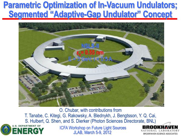
Parametric Optimization of In-Vacuum Undulators ; Segmented “Adaptive-Gap Undulator ” Concept. NSLS-II ε x = 0.55 nm E = 3 GeV , I = 0.5 A.

E N D
Parametric Optimization of In-Vacuum Undulators; Segmented “Adaptive-Gap Undulator” Concept NSLS-IIεx= 0.55 nm E = 3 GeV, I = 0.5 A O. Chubar, with contributions from T. Tanabe, C. Kitegi, G. Rakowsky, A. Blednykh, J. Bengtsson, Y. Q. Cai, S. Hulbert, Q. Shen, and S. Dierker (Photon Sciences Directorate, BNL) ICFA Workshop on Future Light SourcesJLAB, March 5-9, 2012
Outline • Approved NSLS-II Beamlines and IDs • Parametric Optimization of In-Vacuum Undulators • Some Details of Undulator Emission • (inspired by discussions at this Workshop) • 4. Segmented Adaptive-Gap Undulator • - Concept- Magnetic Design Issues- Spectral Performance • 5. Conclusions
NSLS-II “Project”,NEXT, and ABBIX (NIH)Beamlines and IDs PPM: Pure Permanent-Magnet EM: Electro-Magnet H: Hybrid magnetic design † For canted IDs/FEs, ( ) shows canting angle in mrad * Depending on location within ID straight section ** Off-center canting magnet location in ID straight section S. Dierker, Q. Shen, S. Hulbert
Hybrid In-Vacuum Undulator Magnetic Performance,Required Gaps and Acceptable Lengths RADIA Model (central part) IVU Parameters Reference Geometry: Pole Width: 40 mm Pole Height: 25 mm Pole Thickness: 3 mm (for λu = 20 mm) Materials: Pole: VaPermendur NEOMAX Magnet: NdFeB, PrFeB Magnet Width: 50 mm Magnet Height: 29 mm IVU Lengths Satisfying Vertical “Stay Clear” Constraints in Low- and High-Beta Straight Sections Fundamental Photon Energy vs Gapfor Different IVU Periods (E = 3 GeV) βy0 = 3.4 m Max. Lengthin Lo-βSect. Max. Lengthin Hi-βSect. βy0 = 1.06 m
Hybrid In-Vacuum Undulator Magnetic Performance: Halbach Scaling Law Planned SCU for DIAMOND (J. Clarke) Following P. Elleaume, J. Chavanne, B. Faatz, NIM-A 455 (2000), 503-523
Spectral Brightness and Flux at Odd Harmonics of Various IVU in Low-Beta Straight NSLS-II, Low-Beta Straight Section I = 0.5 A; εx = 0.55 nm; εy = 8 pm; σE/E = 8.9x10⁻⁴ Magnet Material: NdFeB, Br = 1.12 T Brightness Flux
Spectral Flux of Different IVUs – IXS “Candidates” – Satisfying E-Beam Vertical “Stay Clear” Constraint Maximal Spectral Flux through 100 μrad (H) x 50 μrad (V) Aperture E-Beam Energy: 3 GeVCurrent: 0.5 A NSLS-II High-Beta (Long) Straight Section ~9.13 keV ~9.13 keV
Spectral Flux of Room-Temperature & Cryogenic IVUs Satisfying E-Beam Vertical “Stay Clear” Constraint IXS Beamline(High-Beta Straight Section; 100 μrad H x 50 μrad V Ap.) ~9.13 keV SRX Beamline(one of two Canted Undulators in Low-Beta Straight Sect.; 150 μrad H x 50 μrad V Ap.) ~4.7 keV
Effect of Electron Beam Energy Spreadon Spectral Flux of IXS IVU22-6 m I = 0.5 A, High-Beta straight section 100 μrad (H) x 50 μrad (V) Aperture 20 x 20 μrad2 Aperture
Single-Electron Undulator Radiation Intensity Distributions “in Far Field” and “at Source” UR “Single-Electron” Intensity and “Multi-Electron” Flux 1:1 Image Plane Ideal Lens Undulator E-Beam Energy: 3 GeV Current: 0.5 A Undulator Period: 20 mm H5 Vertical Cuts (x = 0) Intensity Distributions at 30 m from Undulator Center Intensity Distributions in 1:1 Image Plane “Phase-Space Volume” Estimation for Vertical Plane(RMS sizes/divergences calculated for the portions of intensity distributions containing 95% of flux)
X-Ray Beam Angular Divergence and “Source Size” from Partially-Coherent Wavefront Propagation Simulations Ideal Lens 1:1 Image Plane IVU20 IVU20-3m Spectral Flux through 100 μrad (H) x 50 μrad (V) Aperture at K~1.5 providing H5 peak at ~10 keV Test Optical Scheme Electron Beam: Hor. Emittance: 0.9 nm Vert. Emittance: 8 pm Energy Spread: 8.9x10⁻⁴ Current: 0.5 A Low-Beta Straight Intensity Distributions at ~10 keV At 30 m from Undulator In 1:1 Image Plane Horizontal Cuts (y = 0) Vertical Cuts (x = 0) Horizontal Cuts (y = 0) Vertical Cuts (x = 0) RMS sizes/divergences calculated for the portions of intensity distributions containing 95% of flux …very far from Coherent Gaussian Beam !
Comparison of IVU Spectral Flux (per Unit Surface)for IXS Locations in Low- and High-Beta Straights Spectral Flux of different IVU providing H5 peak at ~9.1 keV E-Beam Energy: 3 GeVCurrent: 0.5 A Flux per Unit Surface (Intensity) Distributions at 20 m from IVUs (ε = 9.13 keV) IVU22-6m in High-Beta Straight Section IVU20-3m in Low-Beta Straight Section Horizontal Cuts (y = 0) Vertical Cuts (x = 0)
IVU22 – 6 m Spectral Flux (per Unit Surface) Near Harmonic Peak Spectral Flux at K~1.5 Providing H5 at ~9.1 keV E-Beam Energy: 3 GeVCurrent: 0.5 A High-Beta (Long) Straight Section Flux per Unit Surface (Intensity) Distributions at 20 m from Undulator Center Horizontal Cuts (y = 0) Vertical Cuts (x = 0)
Possible Next Step on IVU Optimization: Segmented “Adaptive-Gap Undulators” Magnetic Field (NSLS-II IXS BL Example) λu = 22 mm K ≈ 1.5 IVU22 G ≈ 7 mm λu≈ 22.87 mm 20.98 mm 19.74 mm Basic Points about Segmented AGU: K ≈ 1.45 1.57 1.66 G ≈ 7.74 mm 6.23 mm 5.32 mm ● All segments are tuned to the same Resonant Photon Energy ● Vertical Gaps in segments satisfy “Stay-Clear” and Impedance Constraints ● Undulator Period may vary from segment to segment (however it is constant within one Segment) λu≈ 22.54 mm 20.24 mm 19.64 mm 21.26 mm K ≈ 1.47 1.62 1.66 1.55 G ≈ 7.46 mm 5.68 mm 5.25 mm 6.45 mm λu≈ 22.87 mm 19.59 mm K ≈ 1.45 1.67 G ≈ 7.74 mm 5.21 mm
Parameters of AGU “Candidates” for IXS Beamline Room-Temperature AGUE1= 1.824 keV (E5= 9.12 keV) Magnetic Field 21.26 mm λu≈ 19.64 mm 20.24 mm 22.54 mm 1.55 1.47 K ≈ 1.66 1.62 Br = 1.12 T Nper = 331 6.45 mm 7.46 mm G ≈ 5.25 mm 5.68 mm λu≈ 16.61 mm 17.07 mm 18.82 mm Magnetic Field 17.85 mm Room-Temperature AGUE1= 3.04 keV (E3= 9.12 keV) K ≈ 1.177 1.138 0.994 1.072 Br = 1.12 T Nper = 394 G ≈ 5.25 mm 5.68 mm 7.46 mm 6.45 mm Electron Trajectory (after correction) Magnetic Field λu≈ 15.38 mm 15.84 mm 17.58 mm 16.63 mm Cryo-Cooled AGUE1= 3.04 keV (E3= 9.12 keV) K ≈ 1.287 1.244 1.095 1.175 Br = 1.5 T Nper = 423 G ≈ 5.25 mm 5.68 mm 7.46 mm 6.45 mm
“Kick” Angle between AGU Segments Max. electron deflection in Part i Ki/ Max. electron deflection in Part i+1 Ki+1/ Kick Angle at the interface (Ki+1- Ki)/ Part i+1 with Peak Field Bi+1 and period i+1 Part i with Peak Field Bi and period i The large magnetic susceptibility of poles changes the kick angle Ch. Kitegi
Possible AGU Active Correction Scheme • Correction with coils in entrant Ports • Keep coil in air • Compatible with CPMU Part i Part i +1 Ch. Kitegi Part i Part i +1 Initial Trajectory Horizontal Traj [mm] Kick due to Coils Horizontal Traj [mm]
AGU Field and Electron Trajectories Segment junction Segment junction
Spectral Flux of AGU and IVU “Candidates” for NSLS-II IXS Beamline Spectral Flux through 100 μrad (H) x 50 μrad (V) Aperture from Finite-Emittance Electron Beam On-axis Spectral Flux per Unit Surfacefrom Filament Electron Beamat 20 m Observation Distance Ee = 3 GeV, Ie = 0.5 A; NSLS-II High-β (Long) Straight
Approximate (!) Estimation of Spectral Flux at Odd Harmonics of AGU and IVU “Candidates” for IXS Ee = 3 GeV, Ie = 0.5 A; NSLS-II High-β (Long) Straight
Estimation of Spectral Performances of (cryo-)AGU and (cryo-)IVU in Low-Beta Straight of NSLS-II Spectral Flux in 100 μrad (H) x 50 μrad (V) Aperture Ee = 3 GeV, Ie = 0.5 A; NSLS-II Low-β (Short) Straight
Examples of AGU Radiation Intensity Distributions for a Room-Temperature, 7 x 1 m AGU with E1 = 3.04 keV Ee = 3 GeV, Ie = 0.5 A; NSLS-II High-β (Long) Straight Intensity Distributions at 20 m Spectral Flux at 3rd Harmonic Aperture: 100 μrad (h) x 50 μrad (v) Horizontal Cuts (y = 0) Vertical Cuts (x = 0) Shapes of all distributions are very similar to those of a regular undulator…
2D Impedance Analysis of Segmented AGU for NSLS-II Long Straight Section by A. Blednykh Geometries Considered “Constant Gap” “Linear Gap Variation” “Stepped Gap Variation” Longitudinal Short-Range Wakepotential Vertical Short-Range Wakepotential Estimated Longitudinal Loss Factors, Power Losses, and Transverse Kick Factors
Discussion on AGU ● Segmented Adaptive-Gap Undulators (AGUs) allow for most efficient use of space available in (long) Straight Sections of modern Storage Ring sources; ● According to estimations, Room-temperature AGU can offer better spectral performance in Medium-Energy Electron Storage Rings than “standard” Room-temperature IVUs, and even Cryo-cooled IVUs (depending on magnet lattice); ● AGU concept is applicable to ~any magnet technology: AGUs can possibly be made Cryo-cooled, and maybe even Superconducting; ● AGU effects on electron beam seem to be tolerable: “stay-clear” constraint is satisfied “by definition”, impedance seems to be within acceptable limits; heat load on magnet arrays can be tolerable as well; ● AGUs seem to be feasible (at least room-temperature version), from the points of view of magnetic and mechanical designs; ● Production cost of AGU segments can be not very high: assembly and shimming of short segments is simpler than longer ones; mechanics doesn’t need to withstand large forces; overall undulator dimensions can be smaller.
Conclusions on Undulator Optimization The described insertion device design and optimization activity, which is based on high-accuracy calculations in different areas: - (3D) magnetostatics - accelerator physics - synchrotron radiation - thermal and mechanical stress analysis allows to find most appropriate ID parameters for experimental program of every NSLS-II beamline, taking into account all existing constraints and maximally profiting from available magnet technologies and unique features of the NSLS-II storage ring.
Acknowledgments Computer Codes RADIA and SRW were started at ESRF in 1996 These codes are updated from time to time on the ESRF Web site: http://ftp.esrf.fr/pub/InsertionDevices/ • J.-L. Laclare, P. Elleaume • J. Chavanne (ESRF) • M.-E. Couprie, A. Nadji (SOLEIL) • NSLS-II ID and Accelerator Physics Group Tracy was started at LBNL in 1990 Tracy-3is the most recent version available from J. Bengtsson (NSLS-II)
Effects of Different IVUs on Electron Beam Dynamics: “2nd-Order Kicks” From Baseline IVU20 at E = 3 GeV (Radia) In Horizontal Median Plane wpole = Theory: P. Elleaume, EPAC-92 15 μrad J. Bengtsson Tracy-2 Particle Tracking Simulation Results for NSLS-II: 10 5 wpole≥ 40 mm is OK for Low-Beta Straight Section Horizontal Kick 0 wpole≥ 60 mm is OK for High-Beta Straight Section -5 -10 Horizontal Position [mm] From IXS Beamline “Candidate” IVUs In Horizontal Median Plane In Vertical Median Plane The baseline magnetic design, which assumed the use of IVUs in Low-Beta Straight Sections, can hardly be applied for the High-Beta Sections
APPLE-II Undulator Period Choice Radia Model (reduced number of periods) Invented by S. Sasaki Minimal (11.5 mm Gap) and Maximal Photon Energies of the Fundamental Harmonic vsUndulator Period for E = 3 GeV CSX beamline choice: λu= 49 mm Br = 1.25 (NdFeB)
APPLE-II Effect on Electron Beam Linear Vertical Polarization Mode Horizontal Magnetic Field “Roll-Off” In Horizontal Median Plane (Radia) Passive and active compensation schemes of APPLE-II “natural” focusing effects are under investigation based on ESRF, BESSY-II and SOLEIL experiences Tune Shift from 2-nd Order Kick: Horizontal Tune Shift in Low- and High-Beta Straight Sections of NSLS-II Horizontal 2nd Order Kick at E = 3 GeV
Compensation of APPLE-II Dynamic Focusing Effects by Current Strips Idea: I. Blomqvist Implementation at BESSY: J. Bahrdt RADIA EPU Model with Strips in Linear Vertical Polarization Mode Efficient Solving for CurrentsUsing Least-Squares Linear Fit Field Integral (at y=0) from Current Densities: Equivalent Vertical Field Integrals from Dynamic Focusing and from the Current Strips Compensating Currents in Lower Strips Matrix calculated by Radia Current Densities from Field Integral: Vertical (Equivalent) Field Integral [G.cm] Current [A] Since the Dynamic Effectsare Anti-Symmetric vs x: Number of Strips used: 2 x 20 Strip Dims: 2 mm x 0.3 mm x 2 m Horizontal Gap bw Strips: 1 mm Vertical Gap bw Strips: 10.7 mm Max. Current obtained: ~ 2.3 A APPLE-II Vertical Gap: 11.5 mm Horizontal Position [mm] Horizontal Position [mm] Electron Trajectory in 3D Magnetic FieldWithout and With Correction Horizontal Trajectory x0=0, y0=0 before Undulator Horizontal Trajectory Horiz. Position [μm] x0= 4 mm, y0=0 before Undulator x0= -4 mm, y0=0 before Undulator Vertical Trajectory Horizontal Position [μm] Horizontal Position [μm] Vertical Position [μm] Longitudinal Position [mm] Longitudinal Position [mm] Longitudinal Position [mm]
Compensation of APPLE-II Dynamic Focusing Effects by Current Strips in Linear Tilted (45˚) Polarization Mode Equivalent Field Integrals from Dynamic Focusing and from the Current Strips Compensating Currents in Lower Strips Horizontal Vertical “Current Strips” are efficient, however require dedicated additional “Feed-Forward” correction tables… Vertical (Equivalent) Field Integral [G.cm] Horizontal (Equivalent) Field Integral [G.cm] Current [A] Horizontal Position [mm] Horizontal Position [mm] Horizontal Position [mm] dynam. effect dynam. effect Electron Trajectory in 3D Magnetic Field Without and With Correction current strips current strips x0= 0, y0= 0 before Undulator x0= 4 mm, y0= 0 before Undulator x0= -4 mm, y0= 0 before Undulator Horizontal Trajectory Horizontal Trajectory Horizontal Trajectory Horizontal Position [μm] Horizontal Position [μm] Horizontal Position [μm] Vertical Trajectory Vertical Trajectory Vertical Trajectory Vertical Position [μm] Vertical Position [μm] Vertical Position [μm] Longitudinal Position [mm] Longitudinal Position [mm] Longitudinal Position [mm]
Spectral-Angular Distributions of Emission from 2x3.5 m Long Damping Wiggler in “Inline” Configuration Angular Profiles of DW Emission at Different Photon Energies Spectral Flux per Unit Solid Angle Horizontal Profiles FWHM Angular Divergence of DW Emission Vertical Profiles 1/g ≈ 170 μrad
TPW: Magnetic Field, Electron Trajectory and Spectra (in presence of Bending Magnets) On-Axis Magnetic Field in Dispersion Section Upstream BM Downstream BM TPW TPW Field taken from magnetic simulations BM Field is taken from magnetic measurements on a prototype BM with “nose” Longitudinal Position s are approximate Average Electron Trajectory: Horizontal Angle Average Electron Trajectory: Horizontal Position On-Axis Spectral Flux per Unit Surface at 30 m from TPW Electron Energy: 3 GeV Current: 0.5 A Hor. Emittance: 0.9 nm Vert. Emittance: 8 pm Initial Conditions: <x> = 0, <x’>= 0 in TPW Center Spectral Flux through 1.75 mrad (H) x 0.1 mrad (V) Aperture (centered on the axis)
TPW and BM Radiation Intensity Distributions (Hard X-rays) Intensity Distributions at Different Photon Energies at 30 m from TPW Electron Current: 0.5 A Horizontal Cuts at y = 0 Vertical Cuts at x = 0
Angular Power Density Distributions of Radiation from NSLS-II Insertion Devices Undulators and Multi-Pole Wigglers In Horizontal Mid-Plane In Vertical Mid-Plane θX= 1.5 mrad |θX| = 4.75 mrad θX= 0 |θX| ≈ 2.6 mrad Horizontal FWHM Angle: Vertical FWHM Angle: Three-Pole Wiggler and Bending Magnet Radiation at 30 m In Horizontal Mid-Plane NSLS-II: E = 3 GeV, I = 0.5 A
Power Density Distributions of Radiation from NSLS-II Insertion Devices at Fixed Masks (at ~16 m) DW100 (2 x 3.5 m) SCW60 (1 m) TPW P ≈ 61 kW P ≈ 40 kW P ≈ 0.4 kW IVU20 (3 m) IVU21 (1.5 m) IVU22 (6 m) P ≈ 8.1 kW P ≈ 3.6 kW P ≈ 9.4 kW EPU49 (2 x 2 m) LH mode EPU49 (2 x 2 m) LV mode EPU49 (2 x 2 m) LT-45º mode P ≈ 10 kW P ≈ 5.7 kW P ≈ 3.7 kW EPU49 (2 x 2 m) Helical mode P ≈ 7.3 kW NSLS-II: E = 3 GeV, I = 0.5 A IVU, EPU power is given for min. gaps 2 x EPU49 are in canted mode
Radiation Power Density Distributions on Straight Section Chamber Wall for DW90 (9.5 mm int. chamber size) and DW100 (11.5 mm int. chamber size) for “Mis-Steered” E-Beam Magnetic Field NSLS-II: E = 3 GeV, I = 0.5 A High-Beta Straight Section Vertical Projection of “Mis-Steered” Electron Trajectory Horizontal Projection of Electron Trajectory DW100 chamber wall (y = 5.75 mm) DW90 chamber wall (y = 4.75 mm) Power Density Distributions on Chamber Wall “Mis-steered” electron initial conditions: y0 = 2 mm, y0’= 0.25 mrad at z0 ≈ -3.8 m Horizontal Cuts at Longitudinal Position z = 3.9 m DW90 (y = 4.75 mm) DW100 (y = 5.75 mm) Longitudinal Cuts at Horizontal Position x = 0 P ≈ 4.05 kW P ≈ 0.51 kW
EPU49 (2 x 2m) Radiation Power (Helical Mode, 11.5 mm Min. Gap) on Straight Section Chamber Wall at Different Vertical Offsets and Angular Deviations of Electron Beam Power Density Distributions on Chamber Wall in vertical median plane (x = 0) Deposited Power at different e-beam vertical offsets Δy = 3.5 mm Δy’ = 0 at different e-beam vertical angular deviations (applied before undulator) Δy = 0 Δy‘= 0.8 mrad Electron Beam Current: 0.5 A
Results of Vacuum Chamber Heat Conductivity Analysis For “Mis-Steered” Electron Beam in EPU49 (Helical Mode) 1) Δy’ = 0.25 mrad, Δy = 2 mm, Eph= 220 eV 2) Δy’ = 0.25 mrad, Δy = 1.5 mm, Eph= 220 eV ANSYS calculations courtesy of V. Ravindranath P = 1240 W, Tmax = 169.5 °C P = 580 W, Tmax = 128.5 °C 3) Δy’ = 0.25 mrad, Δy = 2 mm, Eph= 270 eV 4) Δy’ = 0.25 mrad, Δy = 2 mm, Eph = 400 eV P = 860 W, Tmax = 136 °C P = 380 W, Tmax = 92.8 °C
Summary of Calculations of Radiation Power Density on Straight Section Vacuum Chamber Walls (or IVU Ni-Cu Foils) for Different NSLS-II IDs Task Force on “Synchrotron Radiation Protection” has been recently created in ASD (headed by P. Ilinsky, Accelerator Physics group) - to treat questions about “mis-steering” assumptions, tolerances, equipment protection schemes, precautions at ID operation, etc.
Estimated Spectral Flux and Brightness of the First Planned NSLS-II Undulators Approximate Spectral Brightness at Odd Harmonics Spectral Flux through Fixed Apertures (200 μrad x 200 μrad for APPLE-II, 150 μrad H x 50 μrad V for IVU in Low-Beta, 100 μrad H x 50 μrad V in High-Beta Straights)
Estimated Spectral Brightness and Flux of Main NSLS-II Radiation Sources Approximate Undulator Spectral Flux Approximate Spectral Brightness at Odd Harmonics Approximate Wiggler Spectral Fluxper Unit Horiz. Angle
Estimated Spectral Brightness of NSLS-II Compared to Other Synchrotron Sources