Download
1 / 28
280 likes | 286 Views
This review outlines the specifications, system overview, installation overview, budget estimations, and production planning for the Beam Loss Monitoring Systems for the LINAC4 and PSB injectors project.

E N D
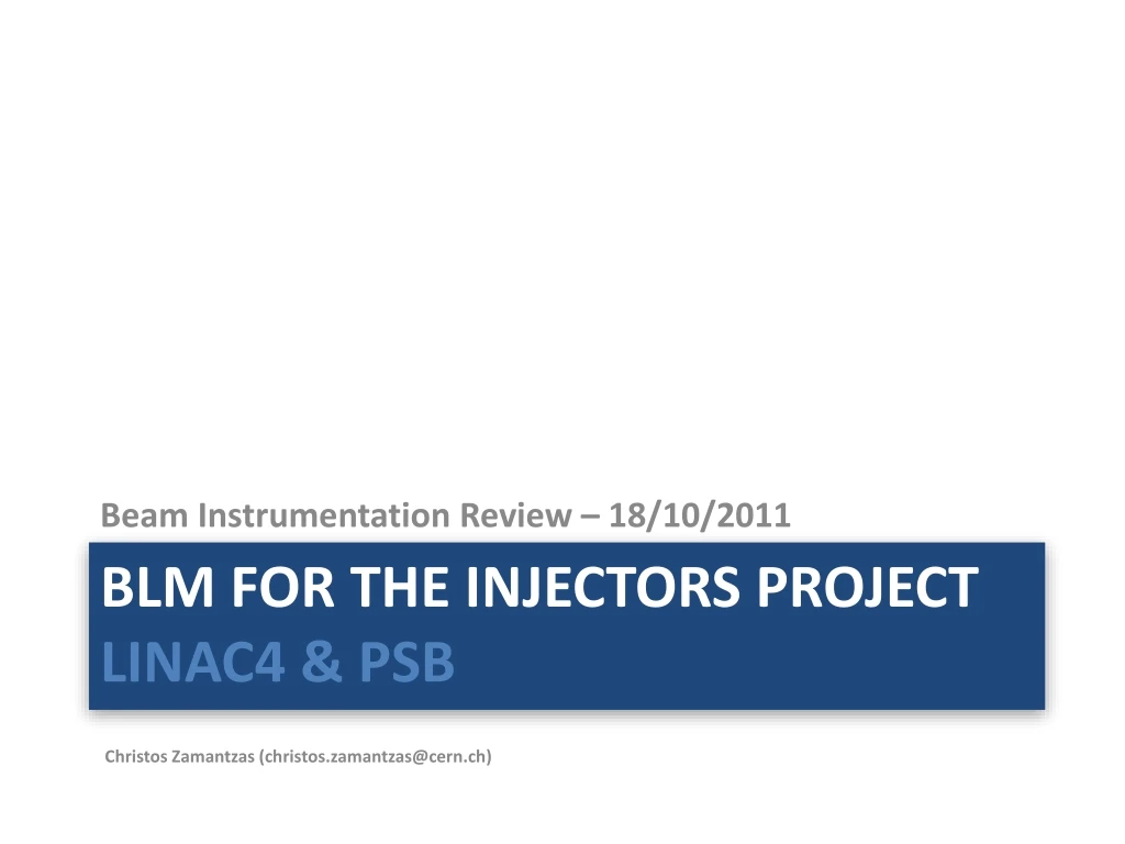
Beam Instrumentation Review – 18/10/2011 BLM for the Injectors project LINAC4 & PSB Christos Zamantzas (christos.zamantzas@cern.ch)
Introduction This project has undertaken the task to develop up-to-date Beam Loss Monitoring Systems for the Injectors. Mainly, • Build a generic, highly configurable and high-performing system • Acquisition part to accept any monitor type • Use reprogrammable parts to target all injectors’ requirements Team members: BI/BL:M. Alsdorf, B. Dehning, E. Effinger, J. Emery, G. Venturini, W. Vigano, C. Zamantzas BI/SW: S. Jackson, L. Jensen BI LINAC4 Review – 18/10/2011
Outline • Specifications • System overview • Installation overview • Budget estimations • Production Planning BI LINAC4 Review – 18/10/2011
General Information Useful information on the LINAC4 and PSB requirements can be found in the following links: • Beam Interlock Specifications for LINAC4, Transfer Lines and PS Booster with LINAC4 [https://edms.cern.ch/document/1016233/0.3] • Notes on the Beam Loss Monitoring System for LINAC4 and PSB [link] • Description of all important info, specific implementations, etc • Documents under preparation. • Meeting notes • Summary table of requirements [link] • Result from discussions the BL and SW sections had with OP BI LINAC4 Review – 18/10/2011
Acquisition & Processing • Synchronisation of acquisitions is required with the start of the cycle to • Perform calculation of integration periods and • Schedule comparisons with their corresponding threshold values. • Synchronisation to be achieved by • Use an event received through the timing system. • Dedicated timing card with broadcast in the backplane. • Sync will be done at the processing level (i.e. 2 samples jitter between cards). • Up to 4 integration periods: • 2 s, 400 s, 1 ms and 1.2 s (full cycle) • Log maximum values recorded for each in the cycle • Log 1.2 s value for ambient radiation measurement BI LINAC4 Review – 18/10/2011
Threshold Comparisons • The threshold values will need to be unique per channel: • Each card will process 8 channels • The threshold values will need to be unique per user: • The information of the current user has to be obtained from the telegram per cycle -> dedicated timing card • Memory for 32 users should be reserved. • Two integration periods, 2 s and 1.2 s, will be checked against their threshold values: • 2 threshold values, one for each of the integration periods. • In the case the measured values exceed those the beam permit signal will be removed for all users and until operator acknowledges. • Two integration periods will be checked for repeated over threshold function (might be implemented in SW) • An additional 2 threshold values for the same integration periods (i.e. 2 s and 1.2 s) will also be required. • In the case they are found to over threshold repeatedly n times it will be required to block this user’s injections only until operator acknowledges. • The repeat value n will be settable per monitor in the range of 1 to 16. BI LINAC4 Review – 18/10/2011
Beam Permit Logic • System has to block injections • i.e. “remove permit” if losses over threshold • System has to remember if the user is allowed to have beam • i.e. “give permit” if previous cycle for the user was ok (or errors cleared) • The Beam Interlock Controller will be configured in the “Non-latch” mode. • i.e. the BLM system will need to follow timing and notify in advance. • The maximum latency (from measurement to output) should be kept as small as possible. • The target for the first integration period is ~ 5 μs. • Only data from the current cycle need to be considered. • Timing in the electronics essential (i.e. possible failure mode) BI LINAC4 Review – 18/10/2011
Online display & Capture functions Cycle n Cycle n+1 C0 C0 2 μs samples LINAC4 Adjustable 1 ms window of 2μs samples 1 ms samples PSB 0 Time [ms] 274 275 875 1200 274 Acq. window Tx window BI LINAC4 Review – 18/10/2011
System Architecture BI LINAC4 Review – 18/10/2011
Acquisition Crate by William Vigano 3D model of the Acquisition Crate • Main panel • LEDs • Power switch • Ref. Input Control Unit Later version w/ advanced remote functions Acquisition cards (BLEDP) BI LINAC4 Review – 18/10/2011
Acquisition principle (ACFC & DADC) by William Vigano • The input channel circuit is able to measure current input from 10pA to 200mA. • The measurement of the current input is performed by two different techniques: • Advanced Current to Frequency Converter (ACFC) used in the range 10pA to 30mA • Direct ADC acquisition (DADC) used in the range 20.3µA to 200mA • No gain change required: • The switch between the 2 ranges is managed by the FPGA. • If the maximum ACFC counts is reached, the FPGA switches the circuit to the DADC mode. • When the value of the DADC falls below a threshold, the FPGA switches the circuit to the ACFC mode. BI LINAC4 Review – 18/10/2011
Cable choices overview Details: • Coaxial (double shielded): CKB50 • HV cable: CBH50 • Connectors (custom-made): prototype received. • Adaptors (custom-made): specifications given BI LINAC4 Review – 18/10/2011
LINAC4 cabling by Ewald Effinger enclosed in cable tray tube HV Supply 1500V HV BNC Ionization Chamber CKB 50 BNC Signal input (CFC) Internal Screen 1 External Screen 2 • External screen to shield high frequency noise. • Internal screen to shield low frequency noise (GND only on electronic side, IC is floating). • Screen of HV BNC is open on the IC side to assure there is no ground loop. • CKB 50 up to 200m, BNC up to 2m Note: most probably will use the same for PS and PSB BI LINAC4 Review – 18/10/2011
Summary of budget needed • LINAC4 calculation still close on estimate • First estimate with new cables on PS (100m) and PSB (60m) • Detectors assumed Ionisation Chambers and taken from the LHC spares * Budget value for LINAC4 is from last EVM * Budget values for PSB and PS are taken from the Injector Consolidation document, which does not include cabling; Note: Latest version of the calculations can be found at: https://espace.cern.ch/project-blm-inj/Shared%20Documents/Budget.xlsx BI LINAC4 Review – 18/10/2011
LINAC4 budget estimate BI LINAC4 Review – 18/10/2011
PSB budget estimate BI LINAC4 Review – 18/10/2011
PCB development • prototype of BLEDP (4 pcs) • Workshop started design on week 34 (mid August) • mount 2 PCB; analogue and digital checks in parallel • Expected mid November • develop basic functions in FPGA • Validate connections; • later will be part of the “diagnostics” firmware. • prototype backplane of acq. crate • Requested time in design office for mid October. • validation of the complete acquisition system • Will use SFP with gigabit Ethernet. • Support by BI/SW for diagnostic and expert application. • prototype mezzanine (if no re-iteration needed) • Requested time for mid November; Will be later • Most of the design is mirror of the digital part of the BLEDP board. -> On plan -> Will receive end Oct. -> Could start end Oct. At the moment we are 3-4 weeks in advance of schedule !! BI LINAC4 Review – 18/10/2011
FPGA & FESA Real-Time software • Definition of the memory map • CPU in readout simulation mode • Start development of driver, RT software, etc. • First version of memory map (LINAC4) - end of September • Develop VME block transfer • Needed for extracting all data requested • First version of (M)BLT – end of November • Test-bench: VME crate with bare carrier boards • Intel CPU • Firmware with dummy vectors • Timing • First version of RT could start being implemented -> two weeks late -> on schedule -> on schedule BI LINAC4 Review – 18/10/2011
Summarising • No written and approved specifications • Continuous communication with OP – most details have been defined • Reliable tunnel installation • Monitors will be Ionisation Chambers • High immunity to EMI with special cables, connectors and enclosed cabletrays • High performance acquisition electronics • Automatic range selection • Dynamic range = 1011 • In system calibration mode • Modular processing electronics • High availability of resources (~350’000 Logic Elements) • Embedded bidirectional gigabit links • Additional gigabit ethernet link • Production and planning well defined and on schedule • Six new printed circuit boards under design • Five FPGAs under design • Test-benches for verification and software development BI LINAC4 Review – 18/10/2011
Prices used for the estimation BI LINAC4 Review – 18/10/2011