Download
1 / 33
920 likes | 2.3k Views
Solenoid Valve Introduction. Pilot Operated. Fs = p . A (N) Fs = Solenoid Pull-force (N) p = Pressure (Pa) (10 5 Pa = 1 bar) A = Orifice area (m 2 ). 2/2 Solenoid Operated Series 210. Centered pilot. Off - centered pilot. VALVE COMPONENTS. OPERATOR VALVE BODY RESILIENTS.

E N D
Pilot Operated Fs = p . A (N) Fs = Solenoid Pull-force (N) p = Pressure (Pa) (105 Pa = 1 bar) A = Orifice area (m2) 2 - File Name - 15/06/2012
2/2 Solenoid Operated Series 210 Centered pilot Off - centered pilot 3
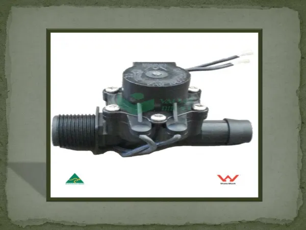
VALVE COMPONENTS • OPERATOR • VALVE BODY • RESILIENTS
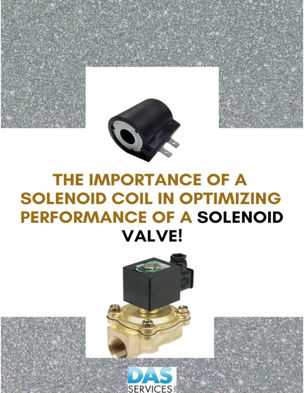
Coil Composition A coil, whether AC or DC, is simply turns of magnet wire on a bobbin, encapsulated to electrical insulation 5 - File Name - 15/06/2012
Coils Cross Section/Copper Package 6 - File Name - 15/06/2012
Magnetism & Solenoid Technology 7 - File Name - 15/06/2012
Magnetic Field When a current is passed through the coiled wire, the electric current generates a magnetic field that causes the magnetic atoms within the iron domains to align. Eventually, the iron reaches its point of maximum magnetism, or saturation, and generates a strong magnetic field. Air core = weak magnetic field Iron core = strong magnetic field 8 - File Name - 15/06/2012
S S N N Induced Currents Michael Faraday proved a changing magnetic field induces an electric current in a wire 9 - File Name - 15/06/2012
Inductance 10 - File Name - 15/06/2012
Electrical Energy to Mechanical Force 11 - File Name - 15/06/2012
AC Solenoids General 15/06/2012
AC Solenoids Inrush and Holding 15/06/2012
DC Solenoids General 15/06/2012
AC Sine Wave A waveform is a representation of how alternating current (AC) varies with time. The most familiar AC waveform is the sine wave, which derives its name from the fact that the current or voltage varies with the sine of the elapsed time. 15 - File Name - 15/06/2012
Current falls to zero 50 Cycle Chatter 16 - File Name - 15/06/2012
Magnetic field induces current in shading coil Low shading coil current provides just enough magnetism to hold the core closed when applied current magnetism is at zero 15/06/2012
Shading Coil for AC Constructions 18 - File Name - 15/06/2012
Shape and Composition of Metal Components AC SBSA DC SBSA Solenoid Base Sub Assembly 19 - File Name - 15/06/2012
Permeability of core & plugnut material Air gap Shape and composition of metal components designed to focus the magnetic field Temperature Factors affecting solenoid performance 20 - File Name - 15/06/2012
Function Breaker Piece Breaker piece 21 - File Name - 15/06/2012
DC Operators Advantages/Disadvantages 22 - File Name - 15/06/2012
AC Operators Advantages/Disadvantages 23 - File Name - 15/06/2012
Coils High class isolation bobbin : 280°C Copper wire with high grade isolation lacquer: ASCO F-coils use N-wire (200°C) ASCO H-coils use double isolation layer. • Coil embedded in Epoxy: • Excellent isolator • Excellent protection against water 24 - File Name - 15/06/2012
General Solenoid valve design How do we find the best solution for the customer ?
TOMSPAVE • T = TYPE • O = OPERATION • M = MEDIUM • S = SIZE, ORIFICE • P = PRESSURE • A = AMBIENT, FLUID • V = VOLTAGE • E = EXTRA’S, ENCLOSURES
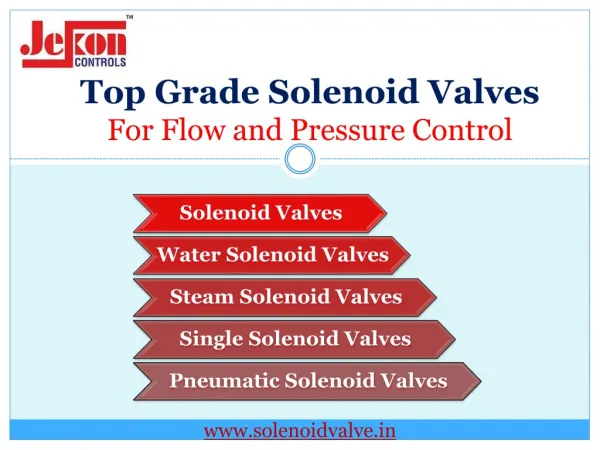
Different valve types Hung diaphragm Floating diaphragm Core disc Basic designs for 2- , 3- , and partly 4- and 5-way constructions
Different valve types • Piston • High pressure • Steam application • Lever • 3/2 steam and light oil • Slide disc • Low pressure steam
Different valve types • Poppet • Heavy duty applications • Less sensitive for dust • More expensive design • Spool • Compact 5/2 design • Cheaper design
HOW TO SELECT THE RIGHT VALVE ? Over 3.000 types of standard valves and more than 20.000 specials The right valve for almost every application; strong and flexible in customer specials.