Download
1 / 6
60 likes | 68 Views
In this work, a pair of LED to LED transceivers had been designed and implemented for bi directional communication between two PCs. Previous work in LED to LED communication relies on software to utilize LED as a light receiver. The problem of such method lies in the difficulty of synchronizing transmitter and receiver. In this work, a fully hardware based solution is implemented using low current Op Amp. The proposed method yields higher baud rate and requires no software overhead microcontroller less . It is also concluded that the maximum communicable distance of the link is inversely proportional with the baud rate. Shaina Suresh, Roger Sim | Dr. Veeraiyah Thangasamy | Vinukumar Luckose | Dr Rekha Labade "Design and Implementation of Bi-Directional Wireless Communication Based on Low-Power LED-to-LED Link" Published in International Journal of Trend in Scientific Research and Development (ijtsrd), ISSN: 2456-6470, Special Issue | International Conference on Advanced Engineering and Information Technology , November 2018, URL: https://www.ijtsrd.com/papers/ijtsrd19145.pdf Paper URL: https://www.ijtsrd.com/computer-science/computer-network/19145/design-and-implementation-of-bi-directional-wireless-communication-based-on-low-power-led-to-led-link/shaina-suresh-roger-sim<br>

E N D
International Journal of Trend in Scientific Research and Development (IJTSRD) International Conference on Advanced Engineering and Information Technology (ICAEIT-2017) nd Implementation of Bi-Directional Wireless Communication Based on Low-Power LED-to-LED Link International Journal of Trend in Scientific Research and Development (IJTSRD) International Conference on Advanced Engineering and Information Technology (ICAEIT ISSN No: 2456 - 6470 | www.ijtsrd.com | Special Issue Publication International Conference on Advanced Engineering ISSN No: 2456 Special Issue Publication Design and Implementation Communication Based Directional Wireless LED Link Shaina Suresh, Roger Sim Linton University College, Mantin, Malaysia Roger Sim Vinukumar Luckose Nilai University, Nilai, Negeri Sembilan, Malaysia, Negeri Sembilan, Malaysia, Vinukumar Luckose Nilai University, Nilai, Linton University College, Dr. Veeraiyah Thangasamy Asia Pacific University, Technology Park, Malaysia Technology Park, Malaysia Thangasamy Dr Rekha Labade Amrutvahini College of Engineering, Dr Rekha Labade Amrutvahini College Sangamner, India Sangamner, India ABSTRACT In this work, a pair of LED-to-LED transceivers had been designed and implemented for bi communication between two PCs. Previous work in LED-to-LED communication relies on software to utilize LED as a light receiver. The problem of such method lies in the difficulty of synchronizing transmitter and receiver. In this work, a fully hardware-based solution is implemented using low current Op-Amp. The proposed method yields higher baud rate and requires no software overhead (microcontroller-less). It is also concluded that the maximum communicable distance of the link is inversely proportional with the baud rate. Keywords: LED-to-LED communication; Visible light communication; Baud rate; Maximum communicable distance; On-Off Keying; Operational amplifier; Comparator; Transition Product; Baud- Distance Product. 1.INTRODUCTION LED (Light Emitting Diode) is a versatile piece of semiconductor. Apart from efficient lighting system, researchers have found use of this component as a wireless communication efficiency, long life, short response time and high modulation rate, etc are some of the properties which contribute to accuracy communication [1]. This method of communication refers to Visible Light Communication (VLC), where refers to Visible Light Communication (VLC), where instead of RF electromagnetic waves, visible light signals are employed for wireless doing so VLC offers unique advantages not found in RF communications, including improved power efficiency (both communication and achieved), secure connection, and less bandwidth (spectrum) restriction. High transmission power, no occupation of radio spectrum, no electromagnetic interference, no electromagneti low energy cost are the most important advantages of VLC [2]. Emerging from its application in mobile phones as backlight, and replacing incandescent lamps in traffic lights, LED’s have found its place in Li-Fi communication due to its feature [3]. However, the disadvantage lies in the fact that VLC uses Line of Sight (LOS) propagation which limits its use to short communication. Various types of sensors have been utilized as light receiver in VLC. These range from high performance photoreceptors, photodiodes, and to a minimum extent, LEDs. The motivation for using LED as a VLC receiver is mainly due (almost) only the wavelengths it emits, thus functioning as a built-in optical f unlike a photodiode, the photocurrent generated within an LED is extremely small, suggesting the use of low-current amplifier. CAN based communication method proposed by [4] shows that wire based CAN method proposed by [4] shows that wire based CAN LED transceivers had instead of RF electromagnetic waves, visible light wireless communication. By VLC offers unique advantages not found in ncluding improved power communication and lighting can be achieved), secure connection, and less bandwidth (spectrum) restriction. High transmission power, no occupation of radio spectrum, no electromagnetic interference, no electromagnetic radiation and very low energy cost are the most important advantages of Emerging from its application in mobile phones as backlight, and replacing incandescent LED’s have found its place in Fi communication due to its high speed ON-OFF feature [3]. However, the disadvantage lies in the fact that VLC uses Line of Sight (LOS) propagation which limits its use to short been designed and implemented for bi-directional communication between two PCs. Previous work in LED communication relies on software to t receiver. The problem of such method lies in the difficulty of synchronizing transmitter and receiver. In this work, a fully based solution is implemented using low- Amp. The proposed method yields higher ware overhead less). It is also concluded that the maximum communicable distance of the link is inversely proportional with the baud rate. LED communication; Visible light communication; Baud rate; Maximum communicable Off Keying; Operational amplifier; Comparator; Transition distance distance wireless wireless time; time; Gain Gain-Bandwidth Various types of sensors have been utilized as light hese range from high performance photoreceptors, photodiodes, and to a minimum extent, LEDs. The motivation for using LED as a LED (Light Emitting Diode) is a versatile piece of semiconductor. Apart from efficient lighting system, ave found use of this component as a wireless communication efficiency, long life, short response time and high etc are some of the properties which due to its sensitivity to the wavelengths it emits, thus in optical filter. However, unlike a photodiode, the photocurrent generated within an LED is extremely small, suggesting the use current amplifier. CAN based communication device. device. High High energy energy of this method of This method of communication @ IJTSRD | Available Online @ www.ijtsrd.com | Special Issue Publication | November 2018 Available Online @ www.ijtsrd.com | Special Issue Publication | November 2018 Available Online @ www.ijtsrd.com | Special Issue Publication | November 2018 P - 222
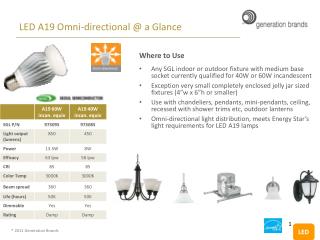
International Journal of Trend in Scientific Research and Deve International Journal of Trend in Scientific Research and Development (IJTSRD) | ISSN: 2456 lopment (IJTSRD) | ISSN: 2456-647 network can be replaced by optical wirel Another work [2] proposes an FPGA based approach but with a compromise on the downlink speed. This paper also proposes replacement of FPGA with microprocessors to enhance the downlink speed. A work on this approach A CPLD based approach in [1] shows that the In this work, a prototype for demonstrating transmission 100Kbits/sec with a Microcontrollers were used in [5], however results show that the synchronization of transmitter and receiver was compromised on with a bit rate of only 240bits/sec. This work proposes a LED communication designed and implemented using discrete components to achieve communication between two laptops. 2.Proposed Method In previous works, LED-to-LED communication is carried out by software as a means to receive light signal using LEDs. In such method, the LED is reverse biased to act as a small capacitor. The software then periodically charges and discharges the LED capacitor, where a low voltage (high discharge) indicates a ‘1’ and vice versa, as shown in the second illustration of Fig 1. However, the difficulty of this method lies in the synchronization. In practice, the transmitter and receiver synchronized, thus leading to erroneous reception, as shown in the third illustration of Fig. 1. In this work, a fully hardware-based implementation is proposed, the design of which is covered below. network can be replaced by optical wireless CAN. Another work [2] proposes an FPGA based approach but with a compromise on the downlink speed. This paper also proposes replacement of FPGA with microprocessors to enhance the downlink speed. A work on this approach A CPLD based approach in [1] In this work, a prototype for demonstrating transmission 100Kbits/sec with a Microcontrollers were used in [5], however results show that the synchronization of transmitter and connecting the system to PC, a USB-to-UART lized as intermediate protocol conversion device. The choice of ubiquitous USB connection ensures that the system works on most PCs. When there is data to be sent (either input from keyboard or a file), the PC sends data through the converted into UART (serial) format by the USB to UART converter. The converter subsequently outputs the data to the light transceiver to be transmitted wirelessly by blinking the LED. The use of UART protocol in transmission has the USB protocol, only one data connecting the system to PC, a USB converter is utilized as intermediate protocol conversion device. The choice of ubiquitous USB connection ensures that the system works on most PCs. When there is data to be sent (either input from keyboard or a file), the PC sends data through the USB port which is then converted into UART (serial) format by the USB to UART converter. The converter subsequently outputs the data to the light transceiver to be transmitted wirelessly by blinking the LED. The use of UART protocol in transmission has the advantage that unlike USB protocol, only one data line is required. In short, the system to an LED-to-LED replacement for UART link. 2.2. Sensor Selection For this application, the sensor for receiving data (visible light pulses) is chosen to be a low Therefore, the system developed is communication. Like photodiode, LED also produces photocurrent when exposed to light, though in a much smaller amount since LED is optimized to emit instead of receive light. As a light sensor, an LED receiver is sensitive to wavelengths equal to or shorter than the predominant wavelength it emits. Hence, an LED light sensor is analogous to a weak photodiode with built-in optical filter. This helps in cancellation of noise induced by ambient lightings, especi fluorescent lamps. For maximal noise cancellation, the LED chosen is to emit light of as short as possible wavelength. Considering the balance of performance and low cost, the LED chosen for this 5 mm white 10 lm LED from Multicomp predominantly emits 450 nm light wave. The intensity vs. wavelength plot is shown in Fig.3. In contrast, a commercial compact fluorescent lamp emits a spectrum of wavelength shown in Fig. 4 which mainly consists of 550 nm and 610 nm. Since the selected LED is sensitive only to wavelengths equal to or shorter than 450 nm, it does not pick up signal from the lamp (ambient lighting) and therefore is able to work properly under the lighting condition. Apart from fluorescent lamp, one other prominent source of noise for the receiver is sunlight, which consists of UV waves much shorter than 450 nm. The solution for this may take the form of a UV filter installed before the receiver LED. 2.3. Transmitter The transmitter LED is driven directly by the transm (TX) pin of the USB-to-UART Converter at 5 or 0 V. UART Converter at 5 or 0 V. speed speed is of of is around 48cm. 48cm. around distance distance a bit rate of only 240bits/sec. This work proposes a LED-to- LED communication designed and implemented using discrete components to achieve communication system to be designed is LED replacement for UART link. For this application, the sensor for receiving data (visible light pulses) is chosen to be a low-cost LED. system developed is an LED to LED communication. Like photodiode, LED also produces photocurrent when exposed to light, though in a much smaller amount since LED is optimized to emit instead of receive light. As a light sensor, an LED er is sensitive to wavelengths equal to or shorter than the predominant wavelength it emits. Hence, an LED light sensor is analogous to a weak photodiode in optical filter. This helps in cancellation of noise induced by ambient lightings, especially fluorescent lamps. For maximal noise cancellation, the LED chosen is to emit light of as short as possible wavelength. Considering the balance of performance and low cost, the LED chosen for this application is a LED communication is oftware as a means to receive light signal using LEDs. In such method, the LED is reverse biased to act as a small capacitor. The software then periodically charges and discharges the LED capacitor, where a low voltage (high discharge) vice versa, as shown in the second illustration of Fig 1. However, the difficulty of this method lies in the synchronization. In practice, the transmitter and receiver synchronized, thus leading to erroneous reception, as d illustration of Fig. 1. In this work, a based implementation is proposed, the are are almost almost never never from Multicomp which light wave. The intensity vs. wavelength plot is shown in Fig.3. In contrast, a commercial compact fluorescent lamp emits a spectrum of wavelength shown in Fig. 4 which mainly consists of 550 nm and 610 nm. Since cted LED is sensitive only to wavelengths equal to or shorter than 450 nm, it does not pick up signal from the lamp (ambient lighting) and therefore is able to work properly under the lighting condition. Apart from fluorescent lamp, one other prominent rce of noise for the receiver is sunlight, which consists of UV waves much shorter than 450 nm. The solution for this may take the form of a UV filter installed before the receiver LED. Fig.1. Synchronization in LED-to communication using software-based reception method to-LED based reception 2.1.System Description Fig. 2 shows the block diagram of the system. The system design emphasizes heavily on the light transceiver. A pair of light transceiver establishes LED- to-LED communication bi-directionally. For Fig. 2 shows the block diagram of the system. The system design emphasizes heavily on the light transceiver. A pair of light transceiver establishes The transmitter LED is driven directly by the transmit directionally. For @ IJTSRD | Available Online @ www.ijtsrd.com | Special Issue Publication | November 2018 Available Online @ www.ijtsrd.com | Special Issue Publication | November 2018 Available Online @ www.ijtsrd.com | Special Issue Publication | November 2018 P - 223
International Journal of Trend in Scientific Research and Deve International Journal of Trend in Scientific Research and Development (IJTSRD) | ISSN: 2456 lopment (IJTSRD) | ISSN: 2456-647 In other words, the transmission uses on whereby a ‘1’ is dictated by the presence of light and a ‘0’ by the absence of it. An 82 Ohm resistor is connected in series with the LED to limit the to approximately 20 mA. The transmitter circuit is shown in Fig. 5. In other words, the transmission uses on-off keying whereby a ‘1’ is dictated by the presence of light and ‘0’ by the absence of it. An 82 Ohm resistor is connected in series with the LED to limit the current to approximately 20 mA. The transmitter circuit is Fig.5. Transmitter circuit Fig.5. Transmitter circuit Fig.2. Block diagram Fig.6. LED equivalent model: current source quivalent model: current source Fig.7. RC circuit exists within an LED receiver t exists within an LED receiver To voltage source, as shown in Fig. 7, it is evident that an RC circuit exists within an LED, thereby contributing to a finite RC rise/fall time. As a receiver, the photocurrent flowing through an LED is extremely small, typically 50 pA. Thus, an ultra- low current OpAmp must be used. Considering the balance of cost and performance, the LMC662 Op-Amp is chosen. The receiving method makes use of the small photocurrent as input bias current to drive the input of the Op-Amp, thus generating a finite voltage which can then be amplified. However, depending on the properties of the Op amount of photocurrent may drive the Op saturation. The RC time previously mentioned may also limit the speed. The solution for this is to connect a shunt resistor, Rs across the input pin to adjust the current to a “just right” amount as well as optimizing the rise/fall (RC) time due to the internal RC circuit. The shunt resistor has to be chosen carefully as too small a value shorts the photocurrent entirely to ground and too large a value will have minimal effect. voltage source, as shown in Fig. 7, it is evident that an RC circuit exists within an LED, thereby contributing to a finite RC rise/fall time. Fig.3. Spectrum of light emitted by selected LED f light emitted by selected LED As a receiver, the photocurrent flowing through an tremely small, typically 50 pA. Thus, an low current OpAmp must be used. Considering the balance of cost and performance, the LMC662 Amp is chosen. The receiving method makes use of the small photocurrent as input bias current to drive Amp, thus generating a finite voltage which can then be amplified. However, depending on the properties of the Op-Amp, the amount of photocurrent may drive the Op-Amp into saturation. The RC time previously mentioned may solution for this is to connect a shunt resistor, Rs across the input pin to adjust the current to a “just right” amount as well as optimizing the rise/fall (RC) time due to the internal RC circuit. The shunt resistor has to be chosen carefully as too Fig.4. Light spectrum emitted by fluorescent lamp rum emitted by fluorescent lamp 2.4. Receiver According to [6], the equivalent model of an LED as a receiver is a current source in parallel with an internal capacitor, as shown in Fig. 6. Transforming the current source According to [6], the equivalent model of an LED as a receiver is a current source in parallel with an internal capacitor, as shown in Fig. 6. Transforming the photocurrent entirely to ground and too large a value will have minimal effect. @ IJTSRD | Available Online @ www.ijtsrd.com | Special Issue Publication | November 2018 Available Online @ www.ijtsrd.com | Special Issue Publication | November 2018 Available Online @ www.ijtsrd.com | Special Issue Publication | November 2018 P - 224
International Journal of Trend in Scientific Research and Development (IJTSRD) | ISSN: 2456-647 Fig. 8 shows the case of Rs being too small. In this case, most of the photocurrent is shorted to ground by the small Rs and very little current biases the Op-Amp input. Consequently, the output barely approaches a valid ‘1’ (5 V). On the other hand, Fig. 9 shows the consequence of Rs being too large. Now, there is enough current to drive the output to valid logic ‘1’. However, Rs is so large that the time constant, RC slows down the transition time considerably. The result is a wider mark ‘1’ than space ‘0’. This is actually the effect if no shunt resistor is connected (Rs → ∞). The mark ‘1’ will be so much wider than the space ‘0’ that the Op-Amp is seen saturated all the time. Amps built-in, the second Op-Amp is used as a comparator. The complete receiver circuit is shown in Fig. 11. The system is realized in hardware as shown in Fig. 12 with the USB-to-UART converter connected. Fig.10. “Just right” Rs results in desirable output Fig.8. Too small Rs results in weak output Fig.11. Complete receiver circuit diagram Fig.9. Too large Rs has minimal optimizing effect Therefore, the goal is to select Rs so that the input and (amplified) output is as shown in Fig. 10 whereby there is sufficient input bias current to drive the OpAmp input and the transition time is optimal. From continuous experiments, it is discovered that a 470 kΩ resistor fits the requirement properly. It must be noted that for this technique, the value of Rs is non-unique for different LED-Op-Amp combinations and therefore experiments have to be performed to decide what value of Rs suits the application. The design of amplifier is presented next. For maximal distance of communication, it is desirable to configure the Op-Amp for maximum gain. However, two limitations of a non-ideal Op-Amp must be considered: the input offset voltage and gain- bandwidth product. The gain must be set in a value that the input offset voltage is not amplified beyond the valid logic ‘1’ and meets the bandwidth requirement of the application. For this work, the application targets a common 9600 baud which is high enough for flicker to be unobservable. Finally, to improve the transition time and more importantly, to maximize the use of the LMC662 which has two Op- Fig.12. LED-to-LED transceiver realized in hardware 3. Results 3.1 Receiver Signal Fig. 13 shows the output of the LMC662 amplifier (first stage) when a ‘5’ is transmitted from the transmitter. The ASCII equivalent of ‘5’ (10101100 LSB first) is received first followed by at least one ‘1’ stop bit. Fig. 14 shows the output signal of the comparator (second stage). It essentially conveys the same information as that of Fig. 13. However, the transition (rise and fall) time of the signal is considerably improved. It is also noticeable on the received signal that the mark ‘1’ is wider than space ‘0’. This suggests that the shunt resistor Rs is slightly too large, the effect of which is discussed previously. Nonetheless, the link is reliable and usable since the mark ‘1’ is not wider than the space ‘0’ by half a bit period. Thus, the decision point of UART (at the middle of the bit period) allows the receiver to recover the original signal. @ IJTSRD | Available Online @ www.ijtsrd.com | Special Issue Publication | November 2018 P - 225
International Journal of Trend in Scientific Research and Development (IJTSRD) | ISSN: 2456-647 axis due to the reason previously mentioned. Thus, if the baud-distance curve is indeed a hyperbola (inversely proportional), it would be meaningful, in such a system to define a parameter of merit: “Baud- Distance Product” (BDP) which dictates the “goodness” of the link. In this work, an average BDP of 21 baud meter is achieved. This means that if, indeed the baud-distance curve extends to the left asymptote (infinity), the system would be able to communicate over 1 m distance at 21 baud. However, this is currently impossible in practice since no LED- to- LED communication has ever achieved a distance of 1 m. Nonetheless, the proposed BDP is a relatively good measure of system performance. Compared to previous works using ADC sensing method [7][8][5], this method sees an improvement in speed for LED-to-LED communication. However, the bi-directionality of a single LED is sacrificed through the use of Op-Amp and hence twice the number of LED must be employed to achieve bi- directional communication. In contrast, this technique is entirely hardware-based and requires no software to perform continuous ADC measurements, as is the case of previous works. Therefore, this allows for a microcontroller-less solution implementation. In addition, the Op-Amp used (LMC662) is cheaper than most microcontrollers equipped with an ADC, which justifies the use of this approach instead of ADC sensing method. 3.3. Power Consumption The light transceiver draws approximately 27 mA of current from the supply of USB-to-UART converter. This translates into an overall system power consumption of 135 mW (excluding the USB-to- UART converter) which qualifies as a low-power USB device. 4.Conclusion In conclusion, a pair of LED-to-LED transceivers has been successfully designed and implemented which allows for short-distance wireless communication between two PCs using light. The receiving mechanism is fully hardware-based. This allows for a microcontroller-less solution. Bi-directionality is achieved through the inclusion of one additional LED as either a complementary transmitter or receiver. The maximum communicable distance is inversely proportional to the baud rate. In this work, an average Baud-Distance Product (BDP) of 21 baud meter is achieved using LMC662 low current Op-Amp. 3.2. Performance Measurement and Analysis The performance (capability) of the LED-to-LED link is evaluated by the amount of distance communicable for a certain baud rate. Therefore, a series of measurements are made in which the communicable distance is measured for various common baud rates. Graphically, the measurement results are represented in the plot of baud vs. distance as shown in Fig. 15. It must be noted that for measurement no. 1, corresponding to 1200 baud, the receiver stopped functioning properly due to the excessively high gain amplifying the input offset voltage beyond the voltage level for valid logic ‘0’. Thus, the gain is decreased manually. This implies that the result in measurement no. 1 (distance = 10 cm) does not reflect the true capability of the LED-to-LED link. Fig.13. First stage (amplifier) output signal for system Fig.14. Second stage (comparator) output signal Fig.15. Baud vs. distance plot As seen from the Baud vs. Distance plot of Fig. 15, the communicable distance is inversely proportional to the baud rate. The shape of the curve suggests a hyperbola, except for point A, corresponding to 1200 baud. Theoretically, point A should be higher in the y @ IJTSRD | Available Online @ www.ijtsrd.com | Special Issue Publication | November 2018 P - 226
International Journal of Trend in Scientific Research and Development (IJTSRD) | ISSN: 2456-647 3.T. Mahajan, “Li-Fi (Light-Fidelity): The 5G Technology in Wireless Communication,” vol.5, no. 5, pp. 125–128, 2017. 5.Acknowledgements The authors are grateful to Faculty of Engineering and Technology for the support in carrying out this work and also to Linton University College for their support to publish the article. 6.References Journal Articles 1.H. Guo and X. Cai, “CPLD-based indoor wireless optical communication utilizing white LED light,” Optoelectron. Microelectron. (AISOMT), 2011 Acad. Int. Symp., no. 74, pp. 187–191, 2011. 4.K. R. Sohn, H. J. Lee, and Y. J. Kim, “Wireless CAN communications based on white LED,” ICUFN 2011 - 3rd Int. Conf. Ubiquitous Futur. Networks, pp. 127–130, 2011. 5.S. Schmid, G. Corbellini, S. Mangold, and T. R. Gross, “An LED-to-LED Communication system with software-based synchronization,” 2012 IEEE Globecom Work. GC Wkshps 2012, pp. 1264–1268, 2012. Visible Light Technol. 6.C. Pohlmann, “Visible light communication,” Semin. Kommun. der Medizintechnik, vol. 11, no. Vlc, pp. 1–14, 2010. 2.J. Rufo, C. Quintana, F. Delgado, J. Rabadan, and R. Perez-Jimenez, modulations and protocols suitable for visible light communications (VLC) channels: Low and medium baud rate communications links,” 2011 IEEE Consum. Commun. Netw. Conf. CCNC’2011, no. Vlc, pp.362–364, 2011. “Considerations on 7.M. Al-rubaiai, “Design and Development of an LED-based Optical Communication System,” 2015, pp. 1689–1699. indoor visible ligth 8.P. Dietz, W. Yerazunis, and D. Leigh, “Very Low- Cost Sensing and Bidirectional LEDs,” UbiComp 2003 Ubiquitous Comput., pp. 175–191, 2003. Communication Using @ IJTSRD | Available Online @ www.ijtsrd.com | Special Issue Publication | November 2018 P - 227