Download
1 / 12
120 likes | 130 Views
Generation of clean energy is one of the main challenges of the 21st century. Solar energy is the most abundantly available renewable energy source which would be supplying more than 50% of the global electricity demand in 2100. Solar cells are used to convert light energy into electrical energy directly with an appeal that it does not generate any harmful bi-products, like greenhouse gasses. The manufacturing of solar cells is actually based on the types of semiconducting or non-semiconducting materials used and commercial maturity. From the very beginning of the terrestrial use of Solar Cells, efficiency and costs are the main focusing areas of research. The definition of so-called emerging technologies sometimes described as including any technology capable of overcoming the Shockley'u201cQueisser limit of power conversion efficiency (33.7 percent) for a single junction device. In this paper, few promising materials for solar cells are discussed including their structural morphology, electrical and optical properties. The excellent state of the art technology, advantages and potential research issues yet to be explored are also pointed out. Md. Samiul Islam Sadek | Dr. M Junaebur Rashid | Dr. Zahid Hasan Mahmood"Emerging Next Generation Solar Cells: Route to High Efficiency and Low Cost" Published in International Journal of Trend in Scientific Research and Development (ijtsrd), ISSN: 2456-6470, Volume-1 | Issue-4 , June 2017, URL: http://www.ijtsrd.com/papers/ijtsrd96.pdf http://www.ijtsrd.com/physics/other/96/emerging-next-generation-solar-cells-route-to-high-efficiency-and-low-cost/md-samiul-islam-sadek<br>

E N D
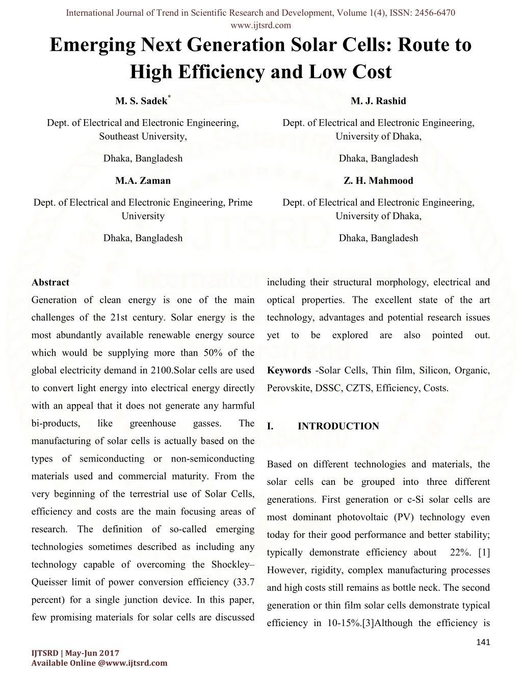
International Journal of Trend in Scientific Research and Development, Volume 1(4), ISSN: 2456-6470 www.ijtsrd.com Emerging Next Generation Solar Cells: Route to High Efficiency and Low Cost M. S. Sadek* M. J. Rashid Dept. of Electrical and Electronic Engineering, Southeast University, Dept. of Electrical and Electronic Engineering, University of Dhaka, Dhaka, Bangladesh Dhaka, Bangladesh M.A. Zaman Z. H. Mahmood Dept. of Electrical and Electronic Engineering, Prime University Dept. of Electrical and Electronic Engineering, University of Dhaka, Dhaka, Bangladesh Dhaka, Bangladesh including their structural morphology, electrical and Abstract Generation of clean energy is one of the main optical properties. The excellent state of the art challenges of the 21st century. Solar energy is the technology, advantages and potential research issues most abundantly available renewable energy source yet to be explored are also pointed out. which would be supplying more than 50% of the global electricity demand in 2100.Solar cells are used Keywords -Solar Cells, Thin film, Silicon, Organic, to convert light energy into electrical energy directly Perovskite, DSSC, CZTS, Efficiency, Costs. with an appeal that it does not generate any harmful bi-products, like greenhouse gasses. The I. INTRODUCTION manufacturing of solar cells is actually based on the types of semiconducting or non-semiconducting Based on different technologies and materials, the materials used and commercial maturity. From the solar cells can be grouped into three different very beginning of the terrestrial use of Solar Cells, generations. First generation or c-Si solar cells are efficiency and costs are the main focusing areas of most dominant photovoltaic (PV) technology even research. The definition of so-called emerging today for their good performance and better stability; technologies sometimes described as including any typically demonstrate efficiency about 22%. [1] technology capable of overcoming the Shockley– However, rigidity, complex manufacturing processes Queisser limit of power conversion efficiency (33.7 and high costs still remains as bottle neck. The second percent) for a single junction device. In this paper, generation or thin film solar cells demonstrate typical few promising materials for solar cells are discussed efficiency in 10-15%.[3]Although the efficiency is 141 IJTSRD | May-Jun 2017 Available Online @www.ijtsrd.com
International Journal of Trend in Scientific Research and Development, Volume 1(4), ISSN: 2456-6470 www.ijtsrd.com less than the c-Si solar cells, the comparative low cost makes it an attractive alternative. The third generation solar cells employ the most advanced techniques which is basically thin film based too, but the varieties of materials used to manufacture such cells introduces a new era of cell design. These cells are made of semiconducting p-n junctions ("first generation") and thin film cells ("second generation"). Common third-generation Fig.1.Graph of efficiency vs. cost for generations of system techniques include multi-layer ("tandem") solar cells. [M. A. Green, "Third Generation cells made of amorphous silicon or III-V compounds Photovoltaics", Springer Verlag, 2003] like gallium arsenide, frequency up down conversion, Intermediate band, hot-carrier effects and other II. Perovskite Solar Cell multiple-carrier ejection techniques.[1-4] A perovskite solar cell is a type of solar cell which In the most advanced PV technology, a wide range of includes a perovskite structured compound, most materials, ranging from semiconducting, non- commonly a hybrid organic-inorganic lead or tin semiconducting, different polymers and even organic halide-based material, as the light-harvesting active are incorporated which actually broadens the choice layer. [5] of materials to manufacture solar cell devices. Not only materials aspect, but also the uses of cutting edge technologies like tandem design of cells, Intermediate band concept, Hot carrier cell, Hybridization of both inorganic and organic materials shows a lots of promises in designing such cells.Some examples of such cell design include - Perovskite solar cell, Copper Zinc Tin Sulfide solar cell (CZTS), and derivate CZTSe and CZTSSe. Dye-Sensitized Solar Cell(DSSC), also known as "Grätzel cell" Fig. 2. Trends in maximum conversion efficiency for solar cells at the research stage Source: Created based on the NREL homepage http://www.nrel.gov/ncpv/images/efficiency_chart.jpg 142 IJTSRD | May-Jun 2017 Available Online @www.ijtsrd.com
International Journal of Trend in Scientific Research and Development, Volume 1(4), ISSN: 2456-6470 www.ijtsrd.com The efficiency has significantly rises from 3/8% in conduction band of TiO2 and collected at the 2009[6] to 21.0% in 2015[7] by using methyl- electrode. These missing electrons are replenished by ammonium lead halides (CH3NH3PbX3) materials as a HTM (Hole Transport Material) mechanism. absorber layer which are cheap and simple to manufacture. With the potential of achieving even higher efficiencies and the very low production costs, perovskite solar cells have become commercially attractive, with start-up companies already promising modules on the market by 2017. [8, 9] Fig. Traditional silicon cells require expensive, multistep 3.Perovskite Solar Cell structure and basic working processes, conducted at high temperatures (>1000 °C) procedure in a high vacuum in special clean room facilities. [10] Meanwhile the organic-inorganic perovskite material There are some very prominent features which makes can be manufactured with simpler wet chemistry perovskite solar cell as one of the best emerging PV techniques in a traditional lab environment. technologies, which includes- A.Perovskite Solar Cell Materials, Structure and Simple manufacturing process (as compared to the operating principles dominant Si based PV technology). [11] The most commonly studied perovskite absorber is methylammonium lead trihalide (CH3NH3PbX3, Bandgap modification by changing the Halide where X is a halogen atom such as iodine, bromine or components as well as their proportion. [12] chlorine), with an optical bandgap between 1.5 eV and 2.3 eV depending on halide content. So by Perovskite materials have very low recombination introducing bandgap tailoring, the optical properties rate. So display a long diffusion length for both of this material can be optimized. holes and electrons of over one micron [13, 14]. The long diffusion length means that these Incoming radiation from the sun is absorbed by the materials can function effectively in thin-film Halide perovskite which is integrated with architecture, and that charges can be transported in mesoporous TiO2 thin film. Electrons generated due the perovskite itself over long distances. to light absorption gets excited and move to the conduction band of perovskite and then jumps to the It has recently been reported that charges in the 143 IJTSRD | May-Jun 2017 Available Online @www.ijtsrd.com
International Journal of Trend in Scientific Research and Development, Volume 1( International Journal of Trend in Scientific Research and Development, Volume 1(4), ISSN: www.ijtsrd.com perovskite material are predominantly present as ), ISSN: 2456-6470 perovskite material are predominantly present as may exist better electrons transporter materials. ectrons transporter materials. free electrons and holes, rather than as bound free electrons and holes, rather than as bound excitons, since the exciton binding energy is low e the exciton binding energy is low Holes transporter (HTM): I ransporter (HTM): It is not stable in enough to enable charge separation at room enough to enable charge separation at room ambient atmosphere temperature.[15] B.Perovskite-Si Tandem Cell D Si Tandem Cell Design Although perovskite Solar Cells exhibiting higher Although perovskite Solar Cells exhibiting higher conversion efficiency with relatively low costs, but conversion efficiency with relatively low costs, but Perovskite cells showing record efficiency beyond Perovskite cells showing record efficiency beyond there are some areas which need to bemastered there are some areas which need to bemastered - 20%, not only efficient but also have a high and 20%, not only efficient but also have a high and tunable bandgap, cheap fabricating techniques makes tunable bandgap, cheap fabricating techniques makes The prime challenges for perovskite solar cells are me challenges for perovskite solar cells are it suitable for application in tandem devices. it suitable for application in tandem devices. inclusion of lead which is detrimental to the device inclusion of lead which is detrimental to the device performance and the aspect of short-term and long term and long- term stability. The water-solubility of the organic solubility of the organic constituent of the absorber material makes makes devices highly prone to rapid degradation in moist highly prone to rapid degradation in moist environments. [16] However, no long term studies , no long term studies and comprehensive encapsulation techniques have yet and comprehensive encapsulation techniques have yet been demonstrated for perovskite solar cells. been demonstrated for perovskite solar cells. Fig.4. Perovskite-Si tandem structure and spectral Si tandem structure and spectral Beside moisture instability, it has some other Beside moisture instability, it has some other response constructional issues need to be addressed. ional issues need to be addressed. This includes - As this silicon cell efficiency record is already very As this silicon cell efficiency record is already very close to the practical efficiency limit of this type of close to the practical efficiency limit of this type of Protective Glass - transparent but not flexible, so transparent but not flexible, so solar cells, perovskite/silicon tandem cells with their solar cells, perovskite/silicon tandem cells with their it can’t be applicable to BIPV type applications. it can’t be applicable to BIPV type applications. potential for ultra-high efficiencies at affordable costs high efficiencies at affordable costs represent the most straight forward way to decrease raight forward way to decrease ITO/FTO electrode - In and Sn are deficient and Sn are deficient the overall cost of photovoltaic systems and the overall cost of photovoltaic systems and materials. In is basically used for display sically used for display purpose consequently also to reduce the price of electricity for consequently also to reduce the price of electricity for and F is harmful for environment and human environment and human end-users. health. TiO2 layers – Acts as electron transporter but, Acts as electron transporter but, 144 IJTSRD | May-Jun 2017 Available Online @www.ijtsrd.com
International Journal of Trend in Scientific Research and Development, Volume 1(4), ISSN: 2456-6470 www.ijtsrd.com CZTS (Copper Zinc Tin Sulfide) Solar Cell: III. department in this area and recently announced a CZTS based solar cell that had a conversion efficiency of 11.1% and could potentially be printed. Copper-zinc-tin-sulfur CZTS-based technology uses [17] This efficiency is lower than the equivalent materials that avoid heavy metals, earth abundant and laboratory records of 19.6% for CIGS and 17.3% for also at a lower cost. The constituents of this CdTe, however CZTS is at a much earlier stage of semiconductor material copper(Cu), zinc(Zn), tin(Sn) development. [18] and sulfur(S), have the advantages of being both abundant in the earth's crust and non-toxic. Some key factors make the IBM solar cells become a viable alternative to existing "thin film" solar cells. These includes – Firstly – It uses rather earth abundant, Nontoxic elements as the constituents. It is well known that in case of CdTe based cell, Tellurium are extremely rare, and Cd is toxic. And in case of CIGS, Indium and Gallium are rare and most widely used in displays. Fig. 5. Normalized abundances of some common PV absorber materials Secondly- An inexpensive ink-based manufacturing process. According to a study done by IBM, thin film solar cells will likely be limited to producing about 0.3 terawatts, but the new cells from IBM could produce an order of magnitude more power. [19] CZTS has numerous advantages that could lead to its massive use as an abundant, non-toxic, low cost absorber for thin film photovoltaic solar cells – Fig. 6.Cost Vs Availability curve of the most used it is a compound whose intrinsic point defects lead solar cell manufacturing materials along with CZTS. to p-type semiconductor behavior. Although such intrinsic point defects levels lead to low charge CZTS also has near ideal properties for solar photo separation, which can be overcome by thanks to voltaics, as it is a very strong absorber and has a band the type-II band alignment of the CZTS/CdS gap of around 1.4eV. IBM has an active research 145 IJTSRD | May-Jun 2017 Available Online @www.ijtsrd.com
International Journal of Trend in Scientific Research and Development, Volume 1(4), ISSN: 2456-6470 www.ijtsrd.com interface. Incorporation of CdS buffer layer A.Potential research issues for CZTS Solar Cells provide excellent band offset and also improves the efficiency a bit. [20] There are still numerous hurdles that must be overcome before a truly competitive kesterite it has a direct bandgap and an absorption coefficient >104 cm-1, which is suitable for thin technology can be validated: [26] film photovoltaic applications [21–23] Necessary to reach 15% efficiency, on par with CdTe and CIGS technologies. Band gap ofthe CZTS thin film can modified from Difficulty in growth of pure kesterite phase 0.94 eV to 1.6 eV by changing the zinc and tin without secondary phases and stannite structure, composition and replacing the selenium (Se) by which are particularly hard to be detected. Optimization of interfaces which is found to be sulfur (S). CZTS belongs to the Kesterites structure and composed of Cu2ZnSnS4 (CZTS), important factor limiting device performance. As Cu2ZnSnSe4 (CZTSe) and CZTSSe are the stated CdS interface with CZTS absorber layer competitors to the CIGS and CdTe based thin film shows excellent band offset, but the incorporation solar cells.This tenability is of particular interest of Cd is not welcome everywhere. Because Cd is for the manufacturing of absorbers with a band one of the six toxic material which hinders both gap between 1.1 and 1.5 eV, which allow environmental and human health acceptance. theoretical efficiencies higher than 30% [24] There are some other potential interfacial materials like ZnS, In2Sn3, ZnSe, ZnxCd1-xS etc., which have their own merits and demerits and It includes Zn and Sn which are respectively performance of the cell largely depends on this. produced in quantity 20 000 and 500 times bigger The long term stability under heat, light, moisture than In which is one of the constituents materials should be confirmed and compared with its sister of CIGS and moreover Indium is used for display competitors like CdTe and CIGS. devices. [25] A truly low-cost and high throughput approach needs to be established, without sacrificing on As CZTS solar cells uses the same structural performance, in order to meet a < $1Wp price morphology as CIGS, so the knowledge gathered target. on back contact, buffer layers and window layer Overall, the proper fabrication process of CZTS, by CIGS scientists can therefore be used and composition of different elements, Grain adapted for CZTS solar cells. boundary, surface quality controlling is yet to be explored. 146 IJTSRD | May-Jun 2017 Available Online @www.ijtsrd.com
International Journal of Trend in Scientific Research and Development, Volume 1(4), ISSN: 2456-6470 www.ijtsrd.com Dye Sensitized Solar Cell IV. Dye Sensitized Solar Cells (DSSCs) are placed in the category of third generation photovoltaics (PV) where new trends in the photovoltaic technology are applied. Among the different possibilities of 3rd generation solar cells DSSC have the most promising prospect due to some attractive features, such as, simpler conventional roll-printing manufacturing techniques, semi-flexible and semi-transparent structure, which Fig.7.DSSC sample structures and working offers some versatile applicable areas to glass-based mechanisms systems, especially in Building Integrated PV(BIPV), and most importantly, the materials used are low-cost. Sunlight passes through the transparent electrode into The overall efficiency of ~12% (for laboratory small the dye layer where it can excite electrons that then size) placed DSSCs as potential inexpensive flow into the titanium dioxide. The electrons flow alternatives to solid state devices. [27] toward the transparent electrode where they are collected for powering a load. After flowing through It is based on a semiconductor formed between a the external circuit, they are re-introduced into the cell photo-sensitized anode and an electrolyte, a photo on a metal electrode on the back, flowing into the electro chemical system. A modern DSSC is electrolyte. The electrolyte then transports the composed of a porous layer of titanium dioxide nano electrons back to the dye molecules. particles, covered with a molecular dye that absorbs sunlight. The titanium dioxide which acts like an There are lots of potential advantages of DSSC, which anode is immersed under an electrolyte solution, are - above which is a platinum-based catalyst which acts like a cathode. DSSCs are attractive as a replacement for existing technologies in "low density" applications like rooftop solar collectors, where the mechanical robustness and light weight of the glass-less collector is a major advantage. In quantum efficiency terms, DSSCs are extremely efficient. Due to their "depth" in the 147 IJTSRD | May-Jun 2017 Available Online @www.ijtsrd.com
International Journal of Trend in Scientific Research and Development, Volume 1(4), ISSN: 2456-6470 www.ijtsrd.com nanostructure there is a very high chance that a most thin-film technologies, is that the cell's photon will be absorbed, and the dyes are very mechanical robustness indirectly leads to higher effective at converting them to electrons. The efficiencies in higher temperatures. DSSCs are quantum efficiency of traditional designs varies, normally built with only a thin layer of conductive depending on their thickness, but are about the plastic on the front layer, allowing them to radiate same as the DSSC. away heat much easier, and therefore operate at lower internal temperatures. Differential kinetics of electron transfer from the Although the DSSC exhibits lots of promises, but Dye to TiO2 provides an extra advantage in case there are still some drawbacks of such cells which of DSSC. The rate of electron generation from the requires more to explore – Dye is very fast and the recombination of the generated electron back to dye is rather very slow process. So as a consequence of this, DSSCs work The major research issue of DSSC design is the even in low-light conditions. DSSCs are therefore use of the liquid electrolyte. This liquid has able to work under cloudy skies and non-direct temperature stability problems. At low sunlight, whereas traditional designs would suffer temperatures the electrolyte can freeze, ending a "cutout" at some lower limit of illumination, power production and potentially leading to when charge carrier mobility is low and physical damage. Higher temperatures cause the recombination becomes a major issue. The cutoff liquid to expand, making sealing the panels a is so low they are even being proposed for indoor serious problem. use, collecting energy for small devices from the lights in the house. [28] In practice it has proven difficult to eliminate a number of expensive materials, notably platinum Temperature hardness is a very remarkable and ruthenium, and the liquid electrolyte presents advantage of the DSSC, which means its a serious challenge to making a cell suitable for performance is remarkably insensitive to use in all weather. temperature change. Thus, raising the temperature from 20 to 60 ºC has no effect on the power The dye molecules are quite small (nanometer conversion efficiency. Stability studies have sized), so in order to capture a reasonable amount shown the DSSC sustain temperatures of 85 ºC of the incoming light the layer of dye molecules without loss of performance. needs to be made fairly thick, much thicker than the molecules themselves. A practical advantage, one DSSCs share with 148 IJTSRD | May-Jun 2017 Available Online @www.ijtsrd.com
International Journal of Trend in Scientific Research and Development, Volume 1(4), ISSN: 2456-6470 www.ijtsrd.com The instability of the dye solar cell was identified exposed surface planes of the oxide and the mode of interaction with the dye. [32] as a main challenge. Its efficiency however, improved during the course of the time by optimizing the porosity, but the instability At this stage the confirmed efficiency obtained remained a problem. [29] with the black dye is 10.4%.[33] A third major drawback is that the electrolyte Further development will concentrate on the solution contains volatile organic compounds (or enhancement of the photo response in the near IR VOC's), solvents which must be carefully sealed region. The goal is to obtain a DYSC having optical as they are hazardous to human health and the features similar to GaAs. A nearly vertical rise of the environment. This, along with the fact that the photocurrent close to the 920 nm absorption threshold solvents permeate plastics, has precluded large- would increase the short circuit photocurrent from scale outdoor application and integration into currently 20.5 to about 28 mA/cm2. With the Voc and flexible structure. [30] FF values would raise the overall efficiency to 14.2%. [34] Replacing the liquid electrolyte with a solid has been a major ongoing field of research. Recent V. Conclusion experiments using solidified melted salts have shown some promise, but currently suffer from A solar cell can be termed as “promising” if the cell higher degradation during continued operation, can be manufactured by using the cheapest as well as and are not flexible. [31] most abundant materials without sacrificing energy- production efficiency. All the solar cell design Most of the small losses that do exist in DSSC's discussed here have the same goal. Perovskite cells are due to conduction losses in the TiO2 and the have received tremendous attention in the public, as clear electrode, or optical losses in the front their research efficiencies recently soared above 20%. electrode. They also offer a wide spectrum of low-cost applications. [35-37] Concerns with the price and availability of indium in CIGS and tellurium in CdTe, For the future improvement of the conversion as well as toxicity of cadmium have been a large efficiency, understanding and control of interfacial motivator to search for alternative thin film solar cell effects are essential, as such type of cells have materials, CZTS as it is composed of earth abundant high contact area of the junction. and non-toxic elements, it can outperform CIGS or CdTe based thin film cells. CZTS have increased It is important to determine the nature of the 149 IJTSRD | May-Jun 2017 Available Online @www.ijtsrd.com
International Journal of Trend in Scientific Research and Development, Volume 1(4), ISSN: 2456-6470 www.ijtsrd.com efficiency to 12.0% in laboratory cells, but more work [5] Collavini, S., Völker, S. F. and Delgado, J. L. is needed for their commercialization. [38] Though (2015). "Understanding the Outstanding Power the DSSC shows a lots of attractive features, it has Conversion Efficiency of Perovskite-Based Solar proven difficult to eliminate a number of expensive Cells”. Angewandte Chemie International Edition materials, notably platinum and ruthenium, and the 54 (34): 9757–9759. liquid electrolyte presents a serious challenge to making a cell suitable for use in all weather. Although [6] Kojima, Akihiro; Teshima, Kenjiro; Shirai, its conversion efficiency is less than the best thin-film Yasuo; Miyasaka, Tsutomu (May 6, 2009). cells, in theory its price/performance ratio should be "Organometal Halide Perovskites as Visible-Light good enough to allow them to compete with fossil Sensitizers for Photovoltaic Cells". Journal of the fuel electrical generation by achieving grid parity. American Chemical Society 131 (17): 6050–6051 [39] [7] NREL Efficiency Chart References [8] Eames, Christopher; Frost, Jarvist M.; Barnes, [1] Shockley, W.; Queisser, H. J. (1961). "Detailed Piers R. F.; o'Regan, Brian C.; Walsh, Aron; Balance Limit of Efficiency of p-n Junction Solar Islam, M. Saiful (2015). "Ionic transport in hybrid Cells". Journal of Applied Physics 32 (3): 510 lead iodide perovskite solar cells". Nature Communications 6: 7497 [2] Green, M. A. (2001). "Third generation photovoltaics: Ultra-high conversion efficiency at [9] Eperon, Giles E.; Stranks, Samuel D.; Menelaou, low cost". Progress in Photovoltaics: Research and Christopher; Johnston, Michael B.; Herz, Laura Applications 9 (2): 123. doi:10.1002/pip.360. M.; Snaith, Henry J. (2014). "Formamidinium lead trihalide: a broadly tunable perovskite for [3] Martí, A.; Luque, A. (1 September 2003). Next efficient planar heterojunction solar cells". Energy Generation Photovoltaics: High Efficiency & Environmental Science 7 (3): 982. through Full Spectrum Utilization. CRC Press. ISBN 978-1-4200-3386-1. [10] Is Perovskite the Future of Solar Cells? Engineering.com. December 6, 2013. [4] Conibeer, G. (2007). "Third-generation photovoltaics". Materials Today 10 (11): 42. [11] oxford-pv-introduction-152.pdf doi:10.1016/S1369-7021(07)70278-X 150 IJTSRD | May-Jun 2017 Available Online @www.ijtsrd.com
International Journal of Trend in Scientific Research and Development, Volume 1(4), ISSN: 2456-6470 www.ijtsrd.com Eperon, Giles E.; Stranks, Samuel D.; [12] Nanotube/Polymer Composites as a Highly Stable Menelaou, Christopher; Johnston, Michael B.; Hole Extraction Layer in Perovskite Solar Cells". Herz, Laura M.; Snaith, Henry J. (2014). "Formamidinium lead trihalide: a broadly tunable [17] M. LaMonica, "IBM Breaks Efficiency Mark perovskite for efficient planar heterojunction solar with Novel Solar Material," Technology Review, cells". Energy & Environmental Science 7 (3): 20 Aug 12. 982 [18] M. A. Green et al., "Solar Cell Efficiency [13] Stranks, S. D.; Eperon, G. E.; Grancini, G.; Tables (Version 40)," Prog. Photovoltaic. Res. Menelaou, C.; Alcocer, M. J. P.; Leijtens, T.; Appl. 20, 606 (2012). Herz, L. M.; Petrozza, A.; et al. (October 17, 2013). "Electron-Hole Diffusion Lengths [19] http://www.solar-facts-and Exceeding 1 Micrometer in an Organometal advice.com/CZTS.html. Trihalide PerovskiteAbsorber". Science 342(6156): 341– [20] S. Chen, X.G. Gong, A. Walsh, S.H. Wei, 344 Appl. Phys. Lett. 96, 021902 (2010) [14] Oxford Researchers Creating Simpler, [21] K. Ito, T. Nakazawa, Jpn J Appl. Phys. 27, Cheaper Solar Cells". SciTechDaily.com. 2094 (1988) November 12, 2013. [22] C.P. Chan, H. Lam, C. Surya, Solar Energy [15] D’Innocenzo, Valerio; Grancini, Giulia; Mater. SolarCells 94, 207 (2010) Alcocer, Marcelo J. P.; Kandada, Ajay Ram Srimath; Stranks, Samuel D.; Lee, Michael M.; [23] W. Xinkun, L. Wei, C. Shuying, L. Yunfeng, Lanzani, Guglielmo; Snaith, Henry J.; et al. (April J. Hongjie,J. Semiconductors 33, 022002 (2012) 8, 2014). "Excitons versus free charges in organo- lead tri-halide perovskites". Nature [24] W. Shockley, H.J. Queisser, J. Appl. Phys. 32, Communications 5 510 (1961) [16] Habisreutinger, Severin N.; Leijtens, Tomas; [25] USGS, Commodity Statistics and Information, Eperon, Giles E.; Stranks, Samuel D.; Nicholas, USGS Minerals Information (2010) Robin J.; Snaith, Henry J. (2014). "Carbon 151 IJTSRD | May-Jun 2017 Available Online @www.ijtsrd.com
International Journal of Trend in Scientific Research and Development, Volume 1(4), ISSN: 2456-6470 www.ijtsrd.com Yanqing Lai, et al,: Current status and future [26] prospects of kesterite CZTS thin film solar cells. [27] Yella A, Lee HW, Tsao HN, Yi C, Chandiran A.K, Nazeeruddin M.K, Diau EW, Yeh CY, Zakeeruddin SM, Grätzel. M. PorphyrinSensitized Solar Cells with Cobalt (II/III)–Based Redox Electrolyte Exceed 12 Percent Efficiency. Science 334, pp. 629-634, (2011) [28] Kimberly Patch, "Solar cell doubles as battery", Technology Research News, 2006 [29] Matsumura, M. et all, "Dye Sensitization and Surface Structures of Semiconductor Electrodes". Ind. Eng. Chem. Prod. Res. Dev. 19 (3): 415– 421(1980). [30] Ecole Polytechnique Fédérale de Lausanne, "New Efficiency Benchmark For Dye-sensitize solar Cells", ScienceDaily, 3 November 2008. [31] Nathalie Rossier-Iten, "Solid hybrid dye- sensitized solar cells: new organic materials, charge recombination and stability", École Polytechnique Fédérale de Lausanne, 2006. 152 IJTSRD | May-Jun 2017 Available Online @www.ijtsrd.com