Download
1 / 13
130 likes | 137 Views
A study to investigate the influence of penstock outlet and the flat blade lateral twist angle on the performance of an existing Pico hydro system was undertaken. Five penstock reduced from76.2 mm to 15, 17.5, 20, 22.5 and 25 mm diameters at the outlet and a runner with adjustable flat blades were fabricated from mild steel sheet. For each of the penstock outlets, five blade twist angles of 50, 55, 60, 75 and 90u00c2u00b0 were tested and the turbine and alternator speed measured with tachometer. The initial and final levels of water in the overhead tank as well as the periods of tests were also measured. The data collected was used to compute the flow rate and power for each set. A maximum computed power of 5600 W was obtained with the 25 mm penstock outlet in conjunction with the blade twist angle of 75o. Also, the maximum speed 1180 rpm of the alternator shaft was obtained for a penstock outlet diameter of about 20.25 mm at the same twist angle of 75o. These results imply that for the system potentially could generate appreciable power using flat blades with the penstock outlets and blade twist angles in the ranges 20 mm and = 600 respectively. Considering the simplicity of the flat blade configuration, the results indicate good promise for providing relatively cheap, clean and convenient domestic power with further work on the system. Daniel T. Ipilakyaa | Alex O. Edeoja | Aondohemen Kulugh "Influence of Penstock Outlet Diameter and Flat Blade Lateral Twist Angle on the Performance of A Simplified Pico Hydropower System" Published in International Journal of Trend in Scientific Research and Development (ijtsrd), ISSN: 2456-6470, Volume-1 | Issue-5 , August 2017, URL: https://www.ijtsrd.com/papers/ijtsrd2322.pdf Paper URL: http://www.ijtsrd.com/engineering/mechanical-engineering/2322/influence-of-penstock-outlet-diameter-and-flat-blade-lateral-twist-angle-on-the-performance-of-a-simplified-pico-hydropower-system/daniel-t-ipilakyaa<br>

E N D
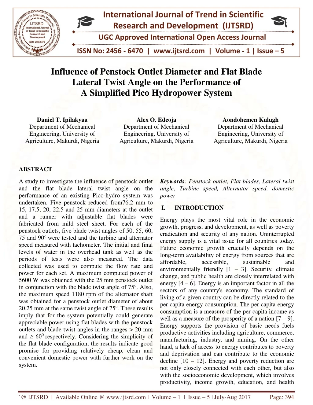
International Journal of Trend in Scientific Research and Development (IJTSRD) UGC Approved International Open Access Journal ISSN No: 2456 - 6470 | www.ijtsrd.com | Volume - 1 | Issue – 5 Influence of Penstock Outlet Diameter and Flat Blade Lateral Twist Angle on the Performance of A Simplified Pico Hydropower System Daniel T. Ipilakyaa Department of Mechanical Engineering, University of Agriculture, Makurdi, Nigeria Alex O. Edeoja Department of Mechanical Engineering, University of Agriculture, Makurdi, Nigeria Aondohemen Kulugh Department of Mechanical Engineering, University of Agriculture, Makurdi, Nigeria ABSTRACT Keywords: Penstock outlet, Flat blades, Lateral twist angle, Turbine speed, Alternator speed, domestic power A study to investigate the influence of penstock outlet and the flat blade lateral twist angle on the performance of an existing Pico-hydro system was undertaken. Five penstock reduced from76.2 mm to 15, 17.5, 20, 22.5 and 25 mm diameters at the outlet and a runner with adjustable flat blades were fabricated from mild steel sheet. For each of the penstock outlets, five blade twist angles of 50, 55, 60, 75 and 90°were tested and the turbine and alternator speed measured with tachometer. The initial and final levels of water in the overhead tank as well as the periods of tests were also measured. The data collected was used to compute the flow rate and power for each set. A maximum computed power of 5600 W was obtained with the 25 mm penstock outlet in conjunction with the blade twist angle of 75o. Also, the maximum speed 1180 rpm of the alternator shaft was obtained for a penstock outlet diameter of about 20.25 mm at the same twist angle of 75o. These results imply that for the system potentially could generate appreciable power using flat blades with the penstock outlets and blade twist angles in the ranges > 20 mm and ≥ 600 respectively. Considering the simplicity of the flat blade configuration, the results indicate good promise for providing relatively cheap, clean and convenient domestic power with further work on the system. I. INTRODUCTION Energy plays the most vital role in the economic growth, progress, and development, as well as poverty eradication and security of any nation. Uninterrupted energy supply is a vital issue for all countries today. Future economic growth crucially depends on the long-term availability of energy from sources that are affordable, accessible, environmentally friendly [1 – 3]. Security, climate change, and public health are closely interrelated with energy [4 – 6]. Energy is an important factor in all the sectors of any country's economy. The standard of living of a given country can be directly related to the per capita energy consumption. The per capita energy consumption is a measure of the per capita income as well as a measure of the prosperity of a nation [7 – 9]. Energy supports the provision of basic needs fuels productive activities including agriculture, commerce, manufacturing, industry, and mining. On the other hand, a lack of access to energy contributes to poverty and deprivation and can contribute to the economic decline [10 – 12]. Energy and poverty reduction are not only closely connected with each other, but also with the socioeconomic development, which involves productivity, income growth, education, and health sustainable and `@ IJTSRD | Available Online @ www.ijtsrd.com | Volume – 1 | Issue – 5 | July-Aug 2017 Page: 394
International Journal of Trend in Scientific Research and Development (IJTSRD) ISSN: 2456-6470 [13 – 15]. Presently, developing nations globally are suffering from disruptions of energy supply in a situation termed energy crisis. Energy crisis implies a situation in which a nation suffers from disruption of energy supply usually accompanied by rapidly increasing energy price and power interruption that threatens both economic and national security. The situation poses serious questions of sustainability, security of supply, and related changes in climate [16 – 19]. Reliance on the fossil fuels, which are finite, for current global energy Understandably, this is causing some fear with devastating consequences for the global economy and quality of life [20, 21]. Ultimately, the near-unlimited supply potential of renewable energy sources should ensure that the world does not fall short of its energy needs. The security of global energy supplies continues to be problematic. Today, oil and gas reserves are in the hands of a small group of nations, several of which are considered politically unstable or have testy relationships with large consuming countries. About 80% the world’s proven oil reserves are located in just three regions in Africa, Russia and the Caspian Basin and the Persian Gulf, with more than half of the world’s remaining proven gas reserves existing in just three countries: Russia, Iran, and Qatar. Concerns over energy security are prompting policymakers to seek independence from foreign sources of energy [22]. In Europe, for instance, new coal-fired power stations are back on the political agenda, partly because Russia is no longer seen as a reliable supplier of gas. In the US, home-grown biofuels have been promoted administrations as an alternative to Middle Eastern oil imports, despite being more expensive. It is envisaged that the more governments can extract themselves from the dependence on foreign energy resources, the greater the likelihood of being energy secured. Also, concerns about global warming primarily as a resulting from the burning of fossil fuels for energy are here. Though some sections of the globe are playing politics with it, the scientific evidence to support this assertion has become increasingly compelling in recent years. Hence, there is a need for urgent and concerted action by all nations to prevent ecological degradation on a massive scale with the attendant fallouts. This can be achieved by switching attention to alternative energy sources such as hydropower [23 – 25]. Nigeria is not left out of the current wave of energy crises. Nigeria is one of the most populated countries in Africa but only about 40% of the people are connected to the energy grid. According to [26], the people who actually have power experience difficulties around 60% of the time and that persistent blackout cripple the industrial sector. Lack of electricity also causes problems for agriculture. Most irrigation lines are run by electricity, so when the power is cut out then the crop yield decreases [27]. Nigeria’s energy grid is arguably in crisis due to lack of development. The key to making a more reliable energy sector is to find and use renewable energy resources, rather than simply relying on the country’s non-renewable resources [28, 29]. Water appears to be the best renewable source of energy because a small-scale hydropower is one of the most cost-effective and reliable energy technologies to be considered for providing clean electricity [30, 31]. Hydropower is a renewable, economic, and environmentally benign Hydropower stations have inherent abilities for instantaneous starting, stopping, load variations and so on, helping to improve the reliability of power systems. Hydro stations are also the best choice for meeting peak demand. The generation cost is not only inflation free but reduces with time and hydroelectric projects have long useful life extending over 50 years and help in conserving scarce and environmentally unfriendly fossil fuels [32 – 34]. Furthermore, they open avenues for development of remote and backward areas. It has been reported that hydropower throughout the world provides around 17% of electricity from the currently installed capacity as well as the ones under construction, making it by far the most important renewable energy for electrical power production. Hydropower production is expected to increase significantly over the next century. Hydropower has remained the renewable source of energy that contributes most to electricity generation. The total estimated annual power generation from hydropower presently has surpassed 3,618 TWh/y [35 – 38]. In Nigeria, hydropower currently accounts for more 29% of the total electrical power supply. The hydropower station at Kainji has an installed capacity is 836 MW with provisions for expansion to 1156 MW. The one at Jebba has an installed capacity of 540 MW. It has been estimated since the 1990s that a total capacity of about 4,650 MW exists for Rivers Kaduna, needs is over 80%. source of energy. by successive `@ IJTSRD | Available Online @ www.ijtsrd.com | Volume – 1 | Issue – 5 | July-Aug 2017 Page: 395
International Journal of Trend in Scientific Research and Development (IJTSRD) ISSN: 2456-6470 Benue and Cross River at Shiroro, Makurdi and Ikom respectively with. Only the Shiroro site has been exploited till date. Estimates for the rivers on the Mambila Plateau are put at 2,330 MW. The overall hydropower resource potentially exploitable in Nigeria is in excess of 11,000 MW. The foregoing assessment is for large hydro schemes which have predominantly been the class of schemes in use prior to the oil crisis of 1973 and still remain so though the current Government is taking definite steps to diversify to renewable sources [39 – 45]. Hydroelectric power plants however have potentially negative environmental impacts. It is not reliable because it depends on the hydrological cycle. Also, global climate change will increase rainfall variability and unpredictability, with the attendant increase in flooding or low water levels will make hydropower production more undependable while posing a major hazard to the safety of dams [40, 46, and 47]. Furthermore, all reservoirs lose storage capacity to sedimentation which can seriously diminish the capacity of dams to generate power. Hydropower projects also alter the habitats of aquatic organisms and affect them directly. Several millions of people have been forcibly evicted from their homes to make way for dams thereby losing their land, livelihoods and access to natural resources while enduring irreparable harm to their cultures and communities. There is also growing evidence suggesting that reservoirs emit significant quantities of greenhouse gases especially in the lowland tropics while communities around them have been reported to be vulnerable to malaria. Also, there is growing evidence that hydropower is often falsely promoted as cheap and reliable, are prone to cost overruns and often do not produce as much power as predicted. The foregoing demerits are more directly applicable to large hydropower schemes. Future plans for new hydroelectric plants, however, will need to consider these major factors and the fact that private capital may not favor it since such facilities do not have short repayment periods and high returns [48, 49]. Small-scale hydropower is a robust and comparatively environmentally benign power generation technology [50 – 52]. However, on this scale, many schemes incur disproportionately high capital costs per installed unit of power. Generally, small hydropower systems may be classified into mini-, micro- and Pico- hydro technologies. Usually, no dam or reservoir storage is involved in Pico-, micro- and mini-hydro schemes. Micro- and Pico-hydro technologies are used in developing countries to provide electricity to isolated communities where the electricity grid is not available, whereas mini-hydro tends to be grid connected [53 – 59]. Micro- and Pico-hydro can scheme design can be approached on a per household basis or at village level often involving local materials and labor whereas mini-hydro schemes require traditional engineering approaches unlike mini-hydro. Also, mini-hydro schemes will usually require an access road to be built for construction materials and heavy electro-mechanical equipment to be delivered to the site, whereas most micro-hydro schemes can be built with purely manual labor in more remote locations. Also, since electricity from micro- and Pico-hydro schemes can be supplied directly to households, there is no large grid to control the frequency and voltage of the supply, hence only a local load controller is necessary. For Pico hydro, the turbine/generator set can be bought as a modular, off- the-shelf unit, unlike the equipment for larger schemes (micro-hydro and upwards) where the specific requirements are taken into consideration in the design/selection of the turbine/generator [60 – 62]. There have been growing interests in research and development into Pico-hydro systems especially in Asian countries. This could have largely been as a result of the need to diversify from fossil fuels, the necessity of off-grid options for better access to rural communities and the natural obstacle which the topography imposes against large scale developments. Implementation is highly advanced leading to significant commercial activities. Discussions are intense and include many different perspectives, from personal experiences highlighting the needs of indigenous people, to the requirements of power intensive industries. Priorities are focused on the need for strategic approaches, and a broader engagement when it comes to energy and water planning. There is also growing interest in the use of pumps as turbines (PATs). This basically involves the use of centrifugal pumps working in the reverse mode. More attention is also currently being given to the pumped-storage hydropower system to supply high peak demands by moving water between reservoirs at different elevations [63 – 66]. The low electrification rate as well as the unsteady nature of power supply in Nigeria hinders the fight against poverty and the development of the country. Apart from the environmental and health hazards posed by fossil fuels which hitherto are the major `@ IJTSRD | Available Online @ www.ijtsrd.com | Volume – 1 | Issue – 5 | July-Aug 2017 Page: 396
International Journal of Trend in Scientific Research and Development (IJTSRD) ISSN: 2456-6470 energy source, there are numerous other challenges such as scarcity, cost and prospect of depletion. This calls for a shift of attention to alternative sources of energy, of which hydro power is one. This has motivated the development of a simple Pico hydropower system. The system has the capacity of mitigating against the shortcomings of conventional hydropower systems while conferring control to the end user and reducing the risks of vulnerability to sabotage and other insurgent activities [26, 29, 42, 67]. The penstock and runner design significantly affects the performance of a Pico hydropower system. This study seeks to find the optimum penstock outlet and the flat blade lateral twist angle of a simplified Pico hydro turbine, in order to improve its performance and provide additional data in this area of study. The general principle revolves around its simplicity and adaptability to locations where there is no naturally flowing water. Moreover, its scalability for better performance has already being proved from previous aspects that have been reported [68 – 71]. The penstock outlets were made from 1.5 mm mild steel sheet and had outlet diameters of 15, 17.5, 20, 22.5 and 25 mm. Figure 2 shows the various diameter penstock outlets. Fig. 2: the Penstock Outlets used for the Study Following the complete fabrication of the runner, it was then clamped to the shaft flange with three M10 bolts and mounted in between two bearings and seals on the already existing turbine casing and cover to allow free spinning of the shaft and prevent leakages in the turbine [70]. The bearings were lubricated to minimize friction. The turbine casing cover was then secured in position with M14 and M13 bolts and the turbine pulley of diameter 605 mm was mounted to the end of the shaft. The experimental set up in this study consisted of a pump rated 2 Hp with a flow capacity of 50 l/min and a locally fabricated turbine connected in a closed loop with the help of PVC piping as penstock, a 2000 liters overhead tank and a 3000 liters underground reservoir. Figure 3 shows a picture of the entire system. The suction pipe of the pump draws water from the underground reservoir to the overhead tank to create a head. Water is released from the overhead tank through the penstock and flows through tapered outlet into the turbine casing. The flow through the turbine is regulated using a gate valve installed before entry to the penstock. The water jet strikes the blades transferring its kinetic energy to the shaft and causing the rotary motion of the rotor. The turbine shaft transmits the torque to a 50 mm diameter pulley fixed to the alternator through a toothed v-belt drive in a step up ratio of 12:1, causing the rotary motion of the alternator shaft, thereby generating a voltage. The water in the turbine casing is directed through an outlet port into an underground reservoir from where it is re-cycled to the overhead tank by the pump. II. MATERIALS AND METHOD The materials for this work were selected based on previous aspects of this work [68 – 71]. Mild steel was used for the entire turbine construction, and was chosen for the reasons of its good weldability, machinability, ductility and toughness, and in addition to the availability of the material at an affordable cost compared to other metals. The runner comprised of a circular hub with 10 flat blades equally spaced around the hub with a blade to hub ratio of about 0.55 as used by [72]. The hub and blades were fabricated from 2 mm and 1.5 mm thick mild steel sheet respectively. The blades were structurally made different from the ones used in earlier aspects of the work by being adjustable so that the test can be carried out at different blade angles. Figure 1 shows the assemble runner with the adjustable blades. Fig. 1: The Adjustable Blade Runner Assembly `@ IJTSRD | Available Online @ www.ijtsrd.com | Volume – 1 | Issue – 5 | July-Aug 2017 Page: 397
International Journal of Trend in Scientific Research and Development (IJTSRD) ISSN: 2456-6470 The adjustable blades of the turbine were adjusted laterally to angles of 50, 55, 60, 75 and 90° one after the other, and for each angle, the penstock outlet was varied from 15 to 25 mm in steps of 2.5 mm. In each case, the rotational speeds of the turbine and alternator shafts were measured using a DT-2268 Contact Type Digital Tachometer. The water levels in the underground and overhead reservoirs before and after each operation were measured using a calibrated dip stick and the duration measured using a stopwatch. The difference in water level for the underground reservoir was used to compute the flow rate Q using the expression: ? =∆? t Where Q is the flow rate in the penstock in m3/s, ∆V is the change in volume of water in the overhead tank in m3 and t is the time of flow in seconds. The gross head available was approximately determined by adding the total height of the penstock (7 m) to the depth of water in the overhead reservoir. The major loses ℎ? were computed using equation 2 defined by [73] as ℎ?=6.87? ?) respective turbine and alternator shaft speeds, and DT, DA the corresponding pulley diameters. ?? ?? These ideal values were then compared with the actual experimental ones and a percentage error computed based on their differences. The alternator shaft speed, computed power and the computed percentage errors were then analyzed for variation at 95% confidence interval based on the twist angles and different penstock outlet diameters. =?? ?? (5) (1) 1.85 ?1.165(? (2) Where V is the flow velocity, D is the penstock diameter; L is pipe length and C the Hazen-Williams coefficient. For plastic pipes C is between 135 and 140 while for steel pipes it is 150. The minor losses were computed using 3 defined by [74] as ??????=?2 2?∑?? (3) Where ?? = Coefficients for pipe shape geometry and area contraction. The net head available was computed by subtracting the total losses from the gross head for each operation. The fluid power was computed using 4. ??= ?? Where ? = torque produced and ? = angular velocity. The ideal or expected values of the alternator shaft speed were computed using 5, where NT, NA are the Fig. 3: The whole Experimental Set up III. RESULTS AND DISCUSSION Figure 4 shows a plot of the alternator shaft speed (NA)against blade lateral twist angle (θ). It is observed that the speed (rpm) of the alternator for 25 mm, 20 mm and 17.5 mm penstock outlet increases at different rates as the blade angle increases from 50o to about 78o and then decreases at 90o. The increase of blade angle increases the tangential (turbine driving) component of the hydraulic force which also increases the drag force. Thus at 780, the drag force balances the driving force, and since hydraulic head is reducing, (4) `@ IJTSRD | Available Online @ www.ijtsrd.com | Volume – 1 | Issue – 5 | July-Aug 2017 Page: 398
International Journal of Trend in Scientific Research and Development (IJTSRD) ISSN: 2456-6470 the speed of the alternator shaft decreases. At 50o its speed (105.2 rpm) is higher than that of the 17.5 mm nozzle but lower than the 25 mm nozzle while the 20 mm nozzle at around 75o yields the highest speed than the rest of the nozzles. Beyond 75° the effective surface area of blade becomes too large so that increase in drag forces results, and thus decreases the speed of the turbine. For 22.5 mm the speed at 50 degrees is highest (480 rpm) but decreases at 52° and then increases to a maximum value of 1015 rpm at 72°. At 60o blade angle the alternator speed is same for 20 mm, 22.5 mm and 25 mm nozzles respectively. This suggests that this angle could be the turning point for this arrangement of the system beyond which the performance deteriorates. In summary 20 mm nozzle at a blade twist angle of 780 shows the best performance while 15 mm nozzle at 500 shows the poorest performance. Generally, the effective jet creation and sufficient blade surface area play a very crucial role in the system performance as with conventional hydropower systems [75 - 80]. Alternator Shaft 1200 1000 Speed (Rpm) 15mm PO 17.5mm PO 20mm PO 22.5mm PO 25mm PO 800 600 400 200 0 50 60 70 80 90 Blade Lateral Twist (°) Fig. 4: Variation of Alternator Shaft Speed with Blade Lateral Twist Angle Figure 5 shows the plot of NA against nozzle diameter. The graph shows that the optimum performance of turbine with the flat blades was obtained with the blade at about 77.5°and the nozzle diameter of 23.8 mm. As can be seen, the speed of 1200 rpm was achieved with the 23.8 mm nozzle. At 61°blade angle, the performance of the 20 mm, 22.5 mm and 25 mm nozzles was similar as it can be seen in the graph. Beyond 77.5° blade angle drag force coupled with reduction in head reduces the speed of the turbine. The poorest performance was obtained with 15 mm nozzle and blade angle at 50°. 1200 Alternator Shaft 90 deg 75 deg 60 deg 55 deg 50 deg 1000 Speed (Rpm) 800 600 400 200 0 15 17 19 21 23 25 Penstock Outlet Diameter (mm) Fig. 5: Variation of Alternator Shaft Speed with Penstock Outlet Diameters Figure 6 shows a graph of the computed power against blade angle. At 50° blade angle, 25 mm nozzle gives the highest power with the power decreasing with decrease in blade angle. The power for the two nozzles (20 mm and 17.5 mm) increased steadily till 65° blade angle and then fell. The 25 mm nozzle gives the highest value of power (6000 W) at 83o blade angle, followed by 22.5 mm nozzle which gave the value of 3700 W at 70o blade angle. At 77° degrees blade angle the two graphs for 20 mm and 17.5 mm nozzle intersect at 250 W. Also at 88° blade angle the 17.5 mm and 22.5 mm nozzle gave the same power output of 2600 W. The results `@ IJTSRD | Available Online @ www.ijtsrd.com | Volume – 1 | Issue – 5 | July-Aug 2017 Page: 399
International Journal of Trend in Scientific Research and Development (IJTSRD) ISSN: 2456-6470 corroborate the fact that larger penstock outlet supports higher flow rates which translates to better performance in terms of power generated [81 - 89]. 6000 Computed Power (W) 5000 4000 15mm PO 17.5mm PO 20mm PO 22.5mm PO 25mm PO 3000 2000 1000 0 50 60 70 80 90 Blade Lateral Twist (0) Fig. 6: Variation of Computed Power against Blade Lateral Twist Angle Figure 7 shows a graph of computed power against penstock diameter. The initial power for 25 mm nozzle was the highest and decreased with decrease in the penstock nozzle diameter. The highest value of power which is 5600 W was obtained with 23 mm nozzle, followed by the 22.5 mm nozzle which produced 3600 W, 3000 W were obtained with 25 mm penstock nozzle. The least value of power was obtained with the 17.5 mm nozzle. At 23 mm nozzle, 20 mm and 17.5 mm nozzles gave the same value of power which is 600 W. 6000 90 deg 75 deg 60 deg 55 deg 50 deg Computed Power (W) 5000 4000 3000 2000 1000 0 15 17 19 21 23 25 Penstock Outlet Diameter (mm) Fig. 7: Variation of Computed Power with Penstock Outlet Diameter Tables 1 to 3 show the results of the analysis of variance of the alternator shaft speed, computed power and error percent based on the difference between the actual and ideal alternator shaft speeds. At 95% confidence interval, table 1 shows that the alternator shaft speed is statistically significantly affected by the penstock outlet (columns) and the blade lateral twist angle (rows). Table 2 also indicates a similar conclusion with regards to the computed power which is to be expected because the power computation involved the alternator shaft speed. However, the variation of the computed power with the penstock outlet was more significant than that with the twist angle. This is probably because the penstock outlet directly affects the generation of the water jet before impact with the blades. Table 3 however, indicates that the variation of the departure of the experimental values of the alternator shaft speed from the ideal values using 5 with the penstock outlets and the blades twist angles were not statistically significant at 95% confidence interval. This could partly be because this departure most likely resulted from the structural and mechanical errors with the turbine rather than the twist angle or the penstock outlet. `@ IJTSRD | Available Online @ www.ijtsrd.com | Volume – 1 | Issue – 5 | July-Aug 2017 Page: 400
International Journal of Trend in Scientific Research and Development (IJTSRD) ISSN: 2456-6470 Table 1: ANOVA of Alternator Speed for the Various Penstock Outlets and Twist Angles Source of Variation Rows 998636 4 249659 Columns 1649108 4 412277 Error 297898.3 16 18618.64 Total 2945642 24 SS df MS F P-value F crit 13.40909 22.14323 5.56E-05 2.34E-06 3.006917 3.006917 Table 2: ANOVA of Computed Power for the Various Penstock Outlets and Twist Angles Source of Variation Rows 4086062 4 1021515 Columns 55722471 4 13930618 65.44567 1.03E-09 3.006917 Error 3405724 16 212857.7 Total 63214257 24 SS df MS F P-value F crit 4.799053 0.009782 3.006917 Table 3: ANOVA for Percentage Errors in Alternator speeds from the ideal values Source of Variation Rows 716.3216 4 179.0804 1.179366 0.357082 3.006917 Columns 1039.934 4 259.9834 1.712167 0.196465 3.006917 Error 2429.514 16 151.8447 Total 4185.77 24 SS df MS F P-value F crit An attempt was made to relate the trends of these loss percentages of the alternator shaft speed from the ideal values. The mean computed loss percent values were plotted against the blade twist angle and the penstock outlet diameters as shown in figures 8 and 9 respectively. The trends in the figures are generally similar which appears to buttress the fact that this parameters are not directly responsible for the loss in alternator shaft speed. However, the figures show an indication of that the ???????? ?????? ≥ 17.5 ??????? ????? ????? > 55° produced the lower loss percentages. These can further strengthen the earlier assertion that for good performance the selection of penstock outlet diameter and lateral twist angle of flat blades for this system should be around these ranges for any further work with this combination of parameters. 34 32 30 Loss (%) 28 26 24 22 ranges and of 20 22.5 ≥ 75° > 45 55 65 75 85 Blade Lateral Twist Angle (°) Fig. 8: Variation of Alternator Speed Loss Percent with Blade Lateral Twist Angle `@ IJTSRD | Available Online @ www.ijtsrd.com | Volume – 1 | Issue – 5 | July-Aug 2017 Page: 401
International Journal of Trend in Scientific Research and Development (IJTSRD) ISSN: 2456-6470 REFERENCES [1]British Petroleum (2017). BP Energy Outlook 2017 Edition. www.bp.com/energyoutlook#BPstats, 9-22, 74- 77, 90-94 [2]International Energy Agency (IEA) (2015). World Energy Outlook. www.iea.org/t&c/, 1 – 12. [3]MDGs, (2015). Nigeria 2015 – Millennium Development Goals End point Report. Available from: www.mdgs.gov.ng [4]Gujba, H., Mulugetta, Y. and Azapagic, A. (2015). The Household Cooking Sector in Nigeria: Environmental Sustainability Assessment, Resources [Online],4, pp. 412-433. www.mdpi.com/journal/resources [5]Ramchandra, P. and Boucar, D. (2011). Green Energy and Technology, 1-15, Springer, London Dordrecht Heidelberg New York [6]Sambo, A.A. (2008a). The Role of Energy in Achieving Millenium (MDGs), Keynote Address at the National Engineering Technology Conference 2008), Ahmadu Bello University, Zaria, 1st April, 2008. [7]Economic Consulting Associates (ECA) (2014). Correlation and causation between energy development and economic growth, pp. 1-18. Available: https://assets.publishing.service.gov.uk/media/57a 089bae5274a EoD_HD116_Jan2014_Energy_Economic_Growt h. pdf [8]Bergasse, E., Paczynski, W., Dabrowski, M. and Dewulf, L. (2013). The Relationship between Energy and Socio-Economic Development in the Southern and Eastern Mediterranean, MEDPRO Technical Report No. Available https://www.ceps.eu/system/files/MEDPRO%20T R27_CASE% 20and%20Socio- economic%20Development_updated_15Feb2013. pdf [9]Science for Environment Policy (SEP) (2013). Relationships between energy consumption and economic growth Commission DG Environment News Alert Service, edited by SCU, The University of the West of England, Bristol. Available from: http://ec.europa.eu/environment/integration/resear ch/newsalert/pdf/312na6en. pdf 45 40 Available at Loss (%) 35 30 25 Available online at 20 15 17 19 21 23 Penstock Outlet (mm) Fig. 9: Variation of Alternator Speed Loss Percent with Penstock Outlet Diameter CONCLUSION and Economic The results obtained indicate that the performance of the system is affected by the penstock outlet diameter and the flat blade lateral twist angle. The ranges of these parameters suitable for this system are ???????? ?????? ???????? ≥ 20 ?? ????? ????? ????? > 60° . Therefore, this is the combination with the best potential for use with the Pico hydro system with possibility for scaling to suit specific requirements of the performance of the system. and Development Goals (NETec From the findings of this investigation, the following recommendations are made for further aspects of the work: 1.Turbine casings used should have adequate provision for the runner not to run through the water so that drag forces on it can be minimized. 2.Standard turbine housing with built in nozzle mounts which allows for large scale adjustments and accommodates different runner sizes should be constructed, as misalignments can have a significant negative effects on turbine efficiency. 3.Larger diameter pipes should be used in transferring water to the overhead tank to sustain the flow cycle though it may be at the expense of justifiable higher cost. 4.Lighter metals such as aluminum should be used in fabricating the runners and blades to reduce inertia and probably performance. 5.Better awareness and technical understanding of the potentials of the Pico-hydro system needs to be fostered at the local and regional levels in Nigeria so that rural electrification projects can be implemented more effectively. 27b2000229/ even a small jet 27/February 2013. from: 20Bergasse_%20Energy% improve turbine investigated. European `@ IJTSRD | Available Online @ www.ijtsrd.com | Volume – 1 | Issue – 5 | July-Aug 2017 Page: 402
International Journal of Trend in Scientific Research and Development (IJTSRD) ISSN: 2456-6470 [10]Shezi, L. (2015). Nearly 60% of Africans have no access to reliable http://www.htxt.co.za/2015/05/08/ africans-have-no-access-to-reliable-electricity/ [11]Pirlogea, C. and Cicea, C. (2012). Econometric perspective of the energy consumption and economic growth relation in European Union, Renewable and Sustainable Energy Reviews, 16, 5718–5726. [12]Saatci, M. and Dumrul, Y. (2013). The Relationship between Energy Consumption and Economic Growth: Evidence from a Structural Break Analysis for Turkey, International Journal of Energy Economics and Policy 3(1), 20-29. [13]WHO, (2015). Health in 2015: From Millennium Development Goals (MDGs) to Sustainable Development Goals (SDGs), 3-11. Available at www.who.int [14]Gujba, H., Mulugetta, Y. and Azapagic, A. (2010). Environmental and economic appraisal of power generation capacity expansion plan in Nigeria, Energy Policy, [Online], 38, 5636–5652. Available: www.elsevier.com/locate/enpol [15]Nnaji, C.E., Uzoma, C.C. and Chukwu J.O. (2010). The Role of Renewable Energy Resources in Poverty Alleviation Development in Nigeria, Continental Journal of Social Sciences, 3, 31-37. [16]Edeoja, A.O., Ibrahim, J.S. and Kucha, E.I. (2015a). Suitability Technology for Addressing the Nigerian Energy Crisis – A review, International Journal of Engineering Inventions, 4(9), pp. 17-40. [17]Shittu, J. (2015). Towards Achieving Sustainable Development for all: Prioritizing Targets for Implementation: Which way forward for Nigeria? Center for Public Policy Alternatives, 1-18. Available: www.cpparesearch.org/wp- content/.../Country-profile-on-SDGs-Nigeria- Final-Version.pdf [18]Lior, N. (2010). Sustainable Energy and Development: The present (2009) Situation and Possible path for the future, Energy, 35, 3976- 3994. [19]World Bank (2006). Technical and Economic Assessment of Off-Grid, Mini-Grid and Grid Electrification Technologies – Summary Report, World Bank Energy Unit; September 2006. [20]British Petroleum (2016). BP Energy Outlook 2016 Edition: Outlook to 2035. Available at www.bp.com/energyoutlook#BPstats, 44, 74-77, 90-94 [21]Akuru, U.B. and Okoro, O.I. (2011). A Prediction on Nigeria’s Oil Depletion Based on Hubbert’s Model and the Need for Renewable Energy, ISRN Renewable Energy, 2011, Article ID 285649, 2011. [22]Srinivasan, C. (2014). Energy Crises and Social Benefit of Solar Energy, Environmental Science and Development, 5(4), 94-95. [23]Kumar, U. S. and Vijayarajan, S. (2017). Feasibility Study of Optimization in Renewable Energy Penetration to an Isolated Hybrid Power Plant, International Journal of Trend in Research and Development, 4(4), 38-46. [24]Oluoti, K., Megwai, G., Pettersson, A., and Richards, T. (2014). Nigerian Wood Waste: A Dependable and Renewable Fuel Option for Power Production, World Journal of Engineering and Technology, 2(3), 234-248 [25]Yuksel, I. (2013). Renewable Energy Status of Electricity Generation for Future Prospect, Renewable Energy, 50, 1037-1043. [26]Aliyu, A., Ramli, A., Saleh, M. (2013). Nigeria electricity crisis: Power generation capacity expansion and environmental Energy, 61(8), 354-367. [27]Kaseke, N. and Hosking, S. G. (2013). Sub- Saharan Africa Electricity Supply Inadequacy: Implications, Eastern Africa Social Science Research Review, 29(2), 113-132. Available: https://www.ajol.info/index.php/eassrr/ article/view/91488 [28]Oyedepo, O. S. (2012). Energy and sustainable development in Nigeria: the way forward, Energy, Sustainability and https://link.springer.com/journal/13705/2/1/page/1 [29]Adejumobi I.A., Adebisi O.I., Oyejide S.A. (2013). Developing Small Hydropower Potentials for Rural Electrification, IJRRAS, 17(1), 105 – 110. [30]Africa Renewable Energy Initiative (AREI), Framework for Transforming Africa to a Renewable Energy Powered Future with Access for All, content/uploads/2016/04/AREI-Framework_ENG- 1.pdf,2015, 11. [31]Bala, E.J. (2013a). Achieving Renewable Energy Potential in Africa, Joint WEC, AUC and APUA Workshop, Addis Ababa, Ethiopia, 17th– 18th June, 2013. [32]Adamkowski, A. (2012). Discharge Measurement Techniques in Hydropower Emphasis on the electricity, htxt.africa, nearly-60-of- ramifications. and Sustainable of Pico-Hydropower Society, 2(1). http://www.arei.org/wp- Systems with Pressure-Time Method, `@ IJTSRD | Available Online @ www.ijtsrd.com | Volume – 1 | Issue – 5 | July-Aug 2017 Page: 403
International Journal of Trend in Scientific Research and Development (IJTSRD) ISSN: 2456-6470 Hydropower - Practice and Application, Dr. Hossein Samadi-Boroujeni (Ed.), ISBN: 978-953- 51-0164-2, InTech, http://www.intechopen.com/books/hydropower- practice-andapplication/some-recent- achievements-in-discharge-measurements [33]Athanas, A. K. and McCormick, N. (2013), Clean Energy that Safeguards Livelihoods: Integrated Assessments to Unleash Full Sustainable Potential for Renewable Energy, Renewable Energy, 49, pp. 25 - 28. [34]Gatte, M.T. and Kadhim, R.A. (2012). Hydro Power, In Energy Conservation, Ed. A. Z. Ahmed, Published by InTech Janeza Trdine 9, 51000 Rijeka, Croatia, 2012, 95– 124. Available at www.intechopen.com. [35]Matewos, M. and Minaye, E. (2017). Designing Portable Micro - Hydro for Small Scale Hydro Power Plant Construction, International Journal of Engineering and Technology, 7(4), 515-518. [36]Lajqi, S., Lajqi, N., Hamidi, B. (2016). Design and Construction of Mini Hydropower Plant with Propeller Turbine, International Journal of Contemporary, Energy, 2(1), 1-13. [37]Von Flowtow, A. (2012). Micro Hydro Penstock Design, Oregon State University Independent Study and Research Fellow Transcript Notation, June 2, 2012. [38]Ohunakin, O. S., Ojolo, S. J. and Ajayi, O. O. (2011), Small Hydropower (SHP) Development in Nigeria, Renewable and Sustainable Energy Reviews, 15, pp. 2006 – 2013. [39]Bala, E.J. (2013b). Renewable Energy and Energy Efficiency Development in Nigeria, Keynote Paper at the 2-day Workshop on Renewable Energy and Energy Efficiency,10th– 11th June, 2013, Nnamdi Azikiwe University, Awka. [40]Olukanmi, D. O., Assessment of Impact of Hydropower Dams Reservoir Outflow on the Downstream River Flood Regime – Hydropower – Practice and Application, Dr. Hossein Sammad-Boroujeni (Ed.). Available from: http://www.intechopen.com/books/hydropower- practice-and-application/assessment-of-impact-of- hydropower-dams-reservoir-overflow-on-the- downstream-river-flood-regime-niger [41]Olusegun, H. D., Adekunle, A. S., Ohijeagbon, I. O., Oladosu, O. A. and Ajimotokan, H. A. (2010). Retrofitting a Hydropower Turbine for the Generation of Clean Electrical Power, USEP: Journal of Research Information in Civil Engineering, 7(2): 61-69 [42]Ajuwape, T. and Ismail, O.S. (2011). Design and Construction of a 5 kW Turbine for a Proposed Micro Hydroelectric Power Plant Installation at Awba Dam University of Ibadan, International Journal of Electrical and Power Engineering, 5(3), 131– 138. [43]Sambo, A.A. (2008b). Overview of Policy Landscape in Africa on SHP Project Development and Management, Paper presented at International Hydropower Conference, Abuja, 2008. [44]Sambo, A.A. (2005). Renewable Energy for rural Development: The Nigerian Perspective, ISESCO Science and Technology Vision, 1, 2005, 12 – 22. [45]WAEA, (2008). Assessment, Ministerial Water for Agriculture and Energy in Africa: The Challenges of Climate Change. Sirte, Libiyan Arab Jamahiriya. 15-17 December 2008. [46]Nikolaisen, P. (2015). 12 Mega dams that changed the world but not necessarily for the better. Available from: http://www.tu.no/artikler/12- megadammer-som-endret-verden/223528 [47]Cunbin, L., Xian, L. and Minxia, W. (2012). Risk Analysis Simulation Evaluation in Hydroelectric Engineering Project, Research Journal Engineering and Technology, 4(14), 2222 – 2226, [48]Finardi, E. C. and Suzzanto, M. R. (2013). Hydro Unit Commitment and Loading Problem for Day Ahead Operation Planning Problem, Electrical Power and Energy Systems, 44, pp. 7 – 16, [49]Liu, P., Nguyen, T., Cai, X. and Jiang, X. (2012). Finding Multiple Optimal Solutions to Optimal Load Distribution Problem in Hydropower Plant, Energies, 5, pp. 1413-1432. [50]Barros, R. M. and Filho, G. L. T. (2012). Small Hydropower and Carbon Credits Revenue for an SHP Project in National Interconnected Systems in Brazil, Renewable Energy, 48, 27 – 34. [51]ESHA, Current Status of Small Hydropower Development in the EU-27,” European Small Hydropower Association, http://www.streammap.esha.be/6.0.html [52]ESHA, Small Hydropower Energy Efficiency Campaign Action (SHERPA) - Strategic Study for the Development of Small Hydro Power (SHP) in the European Union, European Small Hydropower Association, 2008, http://www.esha.be/ Available from: Ecosystems and Hydropower Resource Conference on Model of Economic of Applied Sciences, Salami, A.W. (2012). Isolated and Nigeria’s Experience, 2010, `@ IJTSRD | Available Online @ www.ijtsrd.com | Volume – 1 | Issue – 5 | July-Aug 2017 Page: 404
International Journal of Trend in Scientific Research and Development (IJTSRD) ISSN: 2456-6470 [53]Ramos, H. M., Simão, M. and Kenov, K. N. (2012). Low-Head Energy Conceptual Design and Laboratory Investigation of a Microtubular Hydro Propeller, International Scholarly Research Network (ISRN), Mechanical Engineering, 2012, 1 – 10. [54]Mishra, S., Singal, S. K. and Khatod, D. K. (2011a). Optimal Hydropower Plant - A review, Renewable and Sustainable Energy Reviews, 15, pp. 3862– 3869. [55]Mishra, S., Singal, S. K. and Khatod, D. K. (2011b). Approach for Cost Determination of Electro-Mechanical Equipment in RoR SHP Projects, Smart Grid and Renewable Energy, 2, pp. 63 - 67. [56]UNIDO (2010). UNIDO Projects for the Promotion of Small Hydro Power for Productive Use, UNIDO Evaluation Group, Independent Thematic Review, 20-39. [57]Yassi, Y. and Hasemloo, S. (2010). Improvement of the Efficiency of a New Micro Hydro Turbine at Part Loads due to Installing Guide Vane Mechanism, Energy Management, 51(10), 1970-1975. [58]Alexander, K.V. and Giddens, E.P. (2008a), Micro hydro: Cost-effective, modular systems for low heads, Renewable Energy, 33, pp. 1379 – 1391. [59]ESHA, Small hydro For Developing Countries, Support from Thematic Network on Hydropower Project, European Small Hydropower Association, European Commission, 2006, http://www.esha.be/ [60]Haidar. M.A, Senan, F. M, Noman .A. Taha R. (2012). Utilization of Pico hydro generation in domestic and commercial loads, Renewable and Sustainable energy reviews, 16, 518-524. [61]Ho-Yan, B. (2012). “Design of a Low Head Pico Hydro Turbine for Rural Electrification in Cameroon” A Thesis presented to The University of Guelph. https://dspace.lib.uoguelph.ca/xmlui/handle/10214 /3552 [62]Maher, P. Smith, N.P.A., Williams, A.A. (2003). Assessment of Pico Hydro as an Option for Off Grid Electrification in Kenya, Renewable Energy, 28, 1369-1369. [63]Cobb, B.R and Sharp, K.V. (2013). Impulse Turbine Performance Characteristics and Their Impact on Pico-Hydro Installation, Renewable energy, 50, 959-964. [64]Pascale, A., Urmee, T. and Moore, A. (2011). Life cycle assessment of a community hydroelectric system in rural Thailand, Renewable Energy, 36(11), 2799-2808. [65]Wohlgemuth, M. (2014). Assessment of Pico- hydro power potential in rural Ethiopia, Unpublished Bachelor submitted to the Department for Hydrology and River Basin Management, Technische Universität München [66]Xuhe, W., Baoshan, Z., Lei, T., Jie, Z., Shuliang, C. (2014). Development of a pump-turbine runner based on multi-objective optimization, 27th IAHR Symposium on Hydraulic Machinery and Systems (IAHR 2014), IOP Conf. Series: Earth and Environmental Science 22. [67]Hoyan, B. (2011). Tesla turbine for Pico hydro applications, Guelph Engineering Journal, 4, 1-8. [68]Edeoja, A. O. and Awuniji, L. (2017). Experimental Investigation of the Influence of Penstock Configuration and Angle of Twist of Flat Blades on the Performance of a Simplified Pico-Hydro System, Engineering Research and Science, 2(7), 14-22. [69]Edeoja, A. O., Edeoja, J. A., Ogboji, M. E. (2016a). Effect of Number of Turbine Runner V- Blades on the Performance of a Simple Pico- Hydro System, Accepted for publication in International Journal Technology, Reference 316145147726833. journals.org [70]Edeoja, A. O., Ibrahim, J. S., Kucha, E. I. (2016b). Investigation of the Configuration on the Performance of a Simplified Pico-hydro System. British Journal of Applied Science & Technology, 14(5), 1-11. [71]Edeoja, A. O., Ibrahim, J. S. and Tuleun, L. T. (2016c). Effect of Blade Cross-Section on the Performance of a Simplified Pico-Hydro System, American Journal of Engineering Research (AJER), 5(12), 1 – 9. [72]Edeoja, A.O., Ibrahim, J.S. and Kucha, E.I. (2015b). Conceptual Design of a Simplified Decentralized Pico Hydropower with Provision for Recycling Water. Journal of Multidisciplinary Engineering Science and Technology (JMEST), 2(2), 22 – 34. [73]ESHA, Guide on How to Develop a Small Hydropower Plant, European Small Hydropower Association, 2004, http://www.esha.be/ [74]Cobb, B. R. (2011). Experimental Study of Impulse Turbines and Alternators for Pico-hydropower Generation, A Conversion: A of Science Thesis Installation of Small European Journal of Conversion and of Engineering and number www.iet- Available: Effect of Penstock Retrieved from Permanent Magnet `@ IJTSRD | Available Online @ www.ijtsrd.com | Volume – 1 | Issue – 5 | July-Aug 2017 Page: 405
International Journal of Trend in Scientific Research and Development (IJTSRD) ISSN: 2456-6470 Master degree thesis presented to the department of Mechanical Engineering, University. [75]Alexander, K.V. and Giddens, E.P. (2008b), Optimum Penstocks for Low Head Micro hydro Schemes, Renewable Energy, 33, pp. 507 –519. [76]Alexander, K.V., Giddens, E.P. and Fuller, A. M. (2009a), Axial-flow turbines for low head micro hydro systems, Renewable Energy, 34, pp. 35 – 47. [77]Alexander, K.V., Giddens, E.P. and Fuller, A. M. (2009b). Radial- and mixed-flow turbines for low head micro hydro systems. Renewable Energy, 34(7), 1885 - 1894. [78]Alnakhlani, M. M., Mukhtar, D. A. Himawanto, A. Alkurtehi1 and D. Danardono (2015). Effect of the Bucket and Nozzle Dimension on the Performance of a Pelton Water Turbine, Modern Applied Science, 9(1), 25-33. [79]Chukwuneke J. L., Achebe C. H., Okolie P. C. and Okwudibe H. A. (2014). Experimental Investigation on the Effect of Head and Bucket Splitter Angle on the Power Output of a Pelton Turbine, Journal of Information Engineering and Applications, 4(10), 81-87. [80]Derakhshan, S. and Kasaeian, N. (2012). Optimal design of axial hydro turbine for micro hydropower plants, 26th IAHR Symposium on Hydraulic Machinery Conf.Series:Earth and Environmental Science, 15, (2012) 042029 [81]Maher, P. and Smith N.P.A. (2001). Pico Hydro for Village Power - a Practical Manual for Schemes Up To 5W In Hilly Areas, Micro Hydro Centre – Nottingham Trent University, Available from: http://www.eee.nottingham.ac.uk/picohydro/docu ments.html [82]Maher, P. (2002a), Kenya Case Study 1 at Kathamba and Case Study 2 at Thima. Available from: http://www.eee.nottingham.ac.uk/picohydro/docu ments.html#kenya [83]Maher, P. (2002b), Design and implementation of a 2.2 kW pico hydro serving 110 households, Micro Hydro Centre – Nottingham Trent University, Available http://www.eee.nottingham.ac.uk/picohydro/docu ments.html. [84]Othman, M.M., Razak, Muhammad, N., Wan Mohammad, W., Sopian, K. (2015). A Review of the Pico-Hydro Turbine: Studies International Review of Mechanical Engineering (IREME), 9 https://doi.org/10.15866/ireme.v9i6.5876 [85]Nimje, A. A. and Dhanjode, G. (2015). Pico- Hydro-Plant for Generation in Remote Villages, IOSR Journal of Environmental Science, Toxicology and Food Technology, 9, Issue 1 Ver. III, 59-67. [86]Park, J.H., Lee, N.J., Wata, J.V., Hwang, Y.C., Kim, Y.T. and Lee, Y.H. (2012). Analysis of a Pico hydro turbine performance by runner blade shape using C F D, 26th IAHR Symposium on Hydraulic Machinery and Systems IOP Publishing IOP Conf. Series: Earth and Environmental Science 15(2012) 042031 [87]Sangal, S, Arpit, G, and Dinesh, K. (2013). Review of Optimal Selection of Turbines for Hydroelectric Projects, International Journal of Emerging Technology and Advance Engineering, 3, 424-430. [88]Smith, N. and Bush, S.R (2010). A Light Left in the Dark: The Practice and Politics of Pico Hydro Power in the Load PDR, Energy Policy. 38(1), 116-127. [89]Zainuddin, H., Yahaya, M.S., Laze, J.M., Basar, M.F., and Ibrahim, Design and Development of Pico Hydro Generation System for Energy Storage Using Consuming Water Distributed to Houses. World Academy of Science, Technology, 59, 155-159. on the Propeller Hydro Type, Oregon State (6), 527-535. Small Scale Power Z. (2009). and Systems, IOP Engineering and from: A.J., Basar, M., `@ IJTSRD | Available Online @ www.ijtsrd.com | Volume – 1 | Issue – 5 | July-Aug 2017 Page: 406