Download
1 / 11
110 likes | 114 Views
Flat-slab building structures possesses major advantages over traditional slab-beam-column structures because of the free design of space, shorter construction time, architectural 'u201cfunctional and economical aspects. Because of the absence of deep beams and shear walls, flat-slab structural system is significantly more flexible for lateral loads then traditional RC frame system and that make the system more vulnerable under seismic events. The critical moment in design of these systems is the slab-column connection, i.e., the shear force in the slab at the connection, which should retain its bearing capacity even at maximal displacements. The behavior of flat slab building during earthquake depends critically on 'u02dcBuilding Configuration'. This fact has resulted in to ensure safety against earthquake forces of tall structures hence, there is need to determine seismic responses of such building for designing earthquake resistant structures. Response Spectrum analysis is one of the important techniques for structural seismic analysis. In the present work dynamic analysis of 15 models of multi-storied RCC Flat slab structure is carried out by response spectrum analysis.The BIS guideline in IS 1893:2002 {Clause 7.1} says 'u0153Regular and Irregular Configuration to perform well in an earthquake, a building should possess four main attributes, namely simple and regular configuration, and adequate lateral strength, stiffness and ductility. Buildings having simple regular geometry and uniformly distributed mass and stiffness in plan as well as in elevation, suffer much less damage than buildings with irregular configurations'u009d. Similarly in IS 4326:1993 {Clause 4.4.1} it is mentioned that 'u0153The building should have a simple rectangular plan and be symmetrical both with respect to mass and rigidity so that the center of mass and rigidity of the building coincide with each other.'u009d But the limiting 'u0153plan aspect ratio'u009d and 'u0153Slenderness ratio'u009d for the regular structure is not prescribed.This study is concerned with the behavior of structure having same plan area but different plan aspect ratio (L/B) and slenderness ratio (H/B) under seismic condition. The structures are simulated in ETABS 13 software and analyzed using Response Spectrum method. Renuka Ramteke"Parametric Study Of Multisoried R.C.C. Flat Slab Structure Under Seismic Effect Having Different Plan Aspect Ratio And Slenderness Ratio" Published in International Journal of Trend in Scientific Research and Development (ijtsrd), ISSN: 2456-6470, Volume-1 | Issue-4 , June 2017, URL: http://www.ijtsrd.com/papers/ijtsrd116.pdf http://www.ijtsrd.com/engineering/structural-engineering/116/parametric-study-of-multisoried-rcc-flat-slab-structure-under-seismic-effect-having-different-plan-aspect-ratio-and-slenderness-ratio/renuka-ramteke<br>

E N D
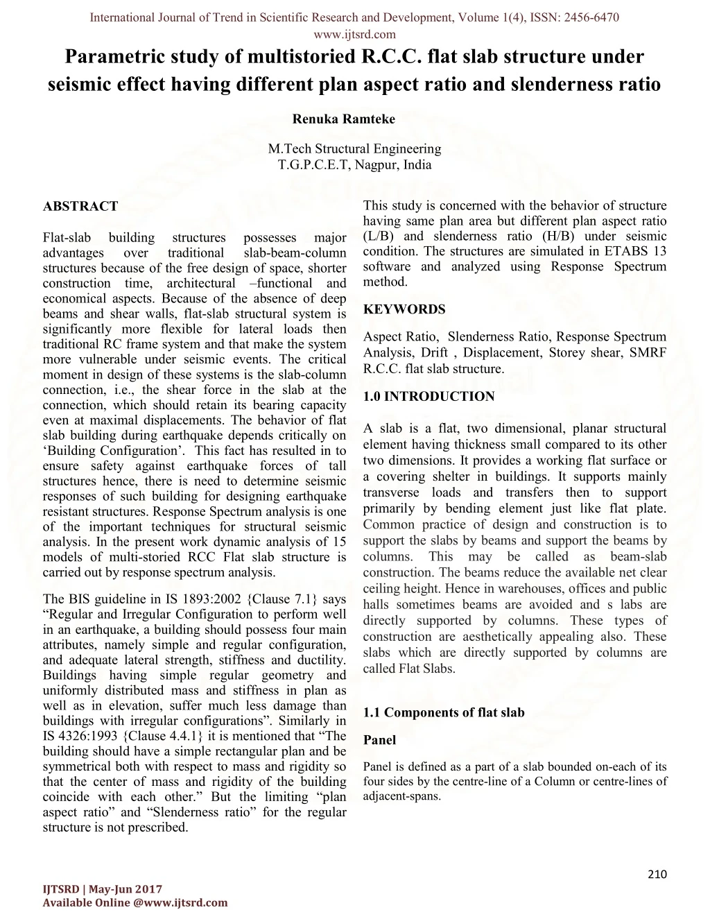
International Journal of Trend in Scientific Research and Development, Volume 1(4), ISSN: 2456-6470 www.ijtsrd.com Parametric study of multistoried R.C.C. flat slab structure under seismic effect having different plan aspect ratio and slenderness ratio Renuka Ramteke M.Tech Structural Engineering T.G.P.C.E.T, Nagpur, India This study is concerned with the behavior of structure having same plan area but different plan aspect ratio (L/B) and slenderness ratio (H/B) under seismic condition. The structures are simulated in ETABS 13 software and analyzed using Response Spectrum method. ABSTRACT Flat-slab advantages structures because of the free design of space, shorter construction time, architectural –functional and economical aspects. Because of the absence of deep beams and shear walls, flat-slab structural system is significantly more flexible for lateral loads then traditional RC frame system and that make the system more vulnerable under seismic events. The critical moment in design of these systems is the slab-column connection, i.e., the shear force in the slab at the connection, which should retain its bearing capacity even at maximal displacements. The behavior of flat slab building during earthquake depends critically on ‘Building Configuration’. This fact has resulted in to ensure safety against earthquake forces of tall structures hence, there is need to determine seismic responses of such building for designing earthquake resistant structures. Response Spectrum analysis is one of the important techniques for structural seismic analysis. In the present work dynamic analysis of 15 models of multi-storied RCC Flat slab structure is carried out by response spectrum analysis. building over structures traditional possesses slab-beam-column major KEYWORDS Aspect Ratio, Slenderness Ratio, Response Spectrum Analysis, Drift , Displacement, Storey shear, SMRF R.C.C. flat slab structure. 1.0 INTRODUCTION A slab is a flat, two dimensional, planar structural element having thickness small compared to its other two dimensions. It provides a working flat surface or a covering shelter in buildings. It supports mainly transverse loads and transfers then to support primarily by bending element just like flat plate. Common practice of design and construction is to support the slabs by beams and support the beams by columns. This may be called as beam-slab construction. The beams reduce the available net clear ceiling height. Hence in warehouses, offices and public halls sometimes beams are avoided and s labs are directly supported by columns. These types of construction are aesthetically appealing also. These slabs which are directly supported by columns are called Flat Slabs. The BIS guideline in IS 1893:2002 {Clause 7.1} says “Regular and Irregular Configuration to perform well in an earthquake, a building should possess four main attributes, namely simple and regular configuration, and adequate lateral strength, stiffness and ductility. Buildings having simple regular geometry and uniformly distributed mass and stiffness in plan as well as in elevation, suffer much less damage than buildings with irregular configurations”. Similarly in IS 4326:1993 {Clause 4.4.1} it is mentioned that “The building should have a simple rectangular plan and be symmetrical both with respect to mass and rigidity so that the center of mass and rigidity of the building coincide with each other.” But the limiting “plan aspect ratio” and “Slenderness ratio” for the regular structure is not prescribed. 1.1 Components of flat slab Panel Panel is defined as a part of a slab bounded on-each of its four sides by the centre-line of a Column or centre-lines of adjacent-spans. 210 IJTSRD | May-Jun 2017 Available Online @www.ijtsrd.com
International Journal of Trend in Scientific Research and Development, Volume 1(4), ISSN: 2456-6470 www.ijtsrd.com 1.2 OBJECTIVES Drops The drops when provided shall be rectangular in plan, and have a length in each direction not less than one-third of the panel length in that direction. For exterior panels, the width of drops at right angles to the non- continuous edge and measured from the centre -line of the columns shall be equal to one -half the width of drop for interior panels. A detailed literature survey is carried out to define the objectives of the thesis. Based on the literature review presented later, the salient objectives of the present study have been identified a follows: Column Head Where column heads are provided, that portion of a column head which lies within the largest right circular cone or pyramid that has a vertex angle of 900 and can be included entirely within the outlines of the column and the column head, shall be considered for design purposes. To perform parametric study on behaviour of multi storied R.C.C. flat slab structure having same plan area but different plan aspect ratio (L/B) and slenderness ratio (H/B), under seismic condition. To perform analysis using Response Spectrum analysis. To study the behaviour of structure situated in seismic Zone III. To study effect on structure due to change in aspect ratio and change in slenderness ratio for structure, under seismic observing results of analysis. Column Strip Column strip means a design strip having a width of 0.25L2, but not greater than 0.25L1, on each side of the column centre-line, where L1 is the span in the direction moments are being determined, measured centre to centre of supports and L2is the span transverse to L1,measured centre to centre of supports condition by Middle Strip Middle strip means a design strip bounded on each of its opposite sides by the column strip. Figure 1.2 Showing structure of flat slab 2.0 LITERATURE REVIEW Figure 1.1 Showing Drop pannel of flat slab The literature survey is carried out in following major areas. These are: “The term Flat slab means a reinforced concrete slab with or without drops, Supported generally without beams, by columns with or without flared column head.” Research papers on response of buildings (regular or irregular configuration) under seismic loading, Importance of Indian seismic design codes and their introduction in brief. 211 IJTSRD | May-Jun 2017 Available Online @www.ijtsrd.com
International Journal of Trend in Scientific Research and Development, Volume 1(4), ISSN: 2456-6470 www.ijtsrd.com Discussion about Building configuration. Literature based on behavior of structure under Seismic condition. 3.1 Material Properties M-30 grade of reinforcing steel are used for all the frame models used in concrete and Fe-415 grade of this study. Elastic material properties of these materials are taken as per Indian Standard IS 456 (2000). The short-term modulus of elasticity (Ec) of concrete is taken as: The first part of this chapter is devoted to a review of published literature related to behavior of building configuration under seismic loading. The response quantities include storey drift, lateral displacement, fundamental modal time frequencies, lateral forces, base shear and mode shapes. period, fundamental ?? = ?5000???MPa (3.1) The second half of this chapter is devoted to a review of design code perspective on Building configuration, Seismic analysis of structure using Response Spectrum method and seismic effect on structure. This part describes different parameters used in analysis of structure and their importance, which will aid in framing the outcomes of analysis. Where, fck= characteristic compressive strength of concrete cube in MPa at 28-day.For the steel rebar, yield stress (fy) and modulus of elasticity (Es) is taken as per IS 456 (2000) Table-2 Material Properties and Geometric Parameters The research paper and literatures collected on the various topics is listed below. Sr. No. Design Parameter Value 1.Rucha S. Banginwar and M. R. Vyawahare, (2012) 2.K S Sable (2012) 3.Arun Solomon (2013) 4.Mohit Sharma, SavitaMaru, (2014) 3.0 MATERIALS AND METHODS Unit concrete weight of 25 kN/m3 1 Characteristic strength of concrete 2 30 MPa Characteristic strength of steel 3 415 MPa Modulus elasticity of steel of 2 x e5 MPa 4 900 meters square 5 Plan area 6 Slab thickness 200 mm 7 Drop thickness 300 mm Table 1- IS Code Used 8 Depth of foundation 3.5m 9 Floor height 3.6m Data assumed for the current study is categorized as followed and presented in tabulated form Material properties and geometric parameters Load considered for designing building Seismic design data 212 IJTSRD | May-Jun 2017 Available Online @www.ijtsrd.com
International Journal of Trend in Scientific Research and Development, Volume 1(4), ISSN: 2456-6470 www.ijtsrd.com Table -3 Load Considered For Analysis Of Building Factor Percentage Damping 10 5% Sr.No. Load Type Value As Dimension and Unit weight of concrete per Special Resisting Frame Moment 11 Type Of Frame Self-weight of Slab and Column 1 The cross sectional dimension of column are shown in table below Dead load of structural components As per IS 875 Part-1 2 Table-5 Cross Sectional Dimension for Column As per IS 875 Part -2 3 Live Load Sr. No. Live load : on Roof and Typical floor Type of Structure Column sizes 4.0 kN/m2 4 G+ 3 (5 storey structure) 600 mm X 600 mm 2.0 kN/m2 5 Floor Finish 1 G+ 5 (7 Storey structure) 600 mm X 600 mm Table-4 Seismic Design Data 2 G+ 7 (9 Storey structure) 600 mm X 600 mm 3 Sr.No. Design Value Parameter G+ 9 (11 Storey structure) 600 mm X 600 mm 4 As Per IS 1893 (Part 1)-2002 G+ 11 (13 Storey structure) 600 mm X 600 mm 1 Earthquake Load 5 Type Foundation Of Isolated Footing Column 2 3.2 Modeling of Structural Element Depth Foundation Of 3 3.5m Beam and columns are modeled as frame elements available in ETABS 15 structural analysis software, with central lines joined at nodes. Column slab joint are considered as rigid slab-column joints. The floor slabs are assumed to act as diaphragms, which ensure integral action of all the vertical lateral load resisting elements. The weight of the slab was distributed as shell load distribution. The columns ends are fixed. A response spectrum analysis applied for analysis of all the 25 models. Type II, Medium As Per IS 1893:2002 4 Type Of Soil Bearing Capacity Of Soil 5 200 kN/m2 6 Seismic Zone IV 7 Zone factor (Z) 0.24 3.3. Method Of Analysis Response reduction factor (R) 8 5 The Present Study Done for the Below Mentioned Analysis 3.3.1 Equivalent static analysis Method 9 1 Importance 213 IJTSRD | May-Jun 2017 Available Online @www.ijtsrd.com
International Journal of Trend in Scientific Research and Development, Volume 1(4), ISSN: 2456-6470 www.ijtsrd.com actual time history record is required. However, it is not possible to have such records at each and every location. Further, the seismic analysis of structures cannot be carried out simply based on the peak value of the ground acceleration as the response of the structure depend upon the frequency content of ground motion and its own dynamic properties. To overcome the above difficulties, earthquake response spectrum is the most popular tool in the seismic analysis of structures. There are computational advantages in using the response spectrum method of seismic analysis for prediction of displacements and member forces in structural systems. The method involves the calculation of only the maximum values of the displacements and member forces in each mode of vibration using smooth design spectra that are the average of several earthquake motions. 3.3.2 Response spectrum method. The steps undertaken in the present study to achieve the above-mentioned objectives area follows: Carry out extensive literature review, to establish the objectives of the research work. Select an exhaustive set of R.C.C. flat slab building models with different number of storey (4 to 12 storeys), Aspect ratio (1to 5) in plan and constant plan area. (900 m2) Perform Response Spectrum Analysis for each of the 25 models. Analyse and compare the result obtained from response spectrum analysis of models which are base shear, storey drift, stiffness, natural time period, and frequency of earthquake. Dropfrom the slab to the column at it support. To resist this negative moment the area at the support needs to be increased, this is facilitated by providing column capital/heads flat slab. The drops when provided shall be rectangular in plan. To resist the punching shear which is predominant at the contact of slab and column Support, the drop dimension should not be less than one -third of panel length in that direction This chapter deals with response spectrum method and its application to various types of the structures. The codal provisions as per IS: 1893 (Part 1)-2002 code for response spectrum analysis of multi-storey building is also summarized. Response spectra are curves plotted between maximum response of SDOF system subjected to specified earthquake ground motion and its time period (or frequency). Response spectrum can be interpreted as the locus of maximum response of a SDOF system for given damping ratio. Response spectra thus helps in obtaining the peak structural responses under linear range, which can be used for obtaining lateral forces developed in structure due to earthquake thus facilitates in earthquake-resistant design of structures. 3.3.1Equivalent static analysis: All design against seismic loads must consider the dynamic nature of the load. However, for simple regular structures, analysis by equivalent linear static methods is sufficient. This is permitted in most codes of practice for regular, low- to medium-rise buildings. This procedure does not require dynamic analysis, however, it account for the dynamics of building in an approximate manner. The static method is the simplest one-it requires less computational efforts and is based on formulate given in the code of practice. First, the design base shear is computed for the whole building, and it is then distributed along the height of the building. The lateral forces at each floor levels thus obtained are distributed to individual’s lateral load resisting elements. Usually response of a SDOF system is determined by time domain or frequency domain analysis, and for a given time period of system, maximum response is picked. This process is continued for all range of possible time periods of SDOF system. Final plot with system time period on x-axis and response quantity on y-axis is the required response spectra pertaining to specified damping ratio and input ground motion. Same process is carried out with different damping ratios to obtain overall response spectra. 3.3.2 Response spectrum method In order to perform the seismic analysis and design of a structure to be built at a particular location, the 214 IJTSRD | May-Jun 2017 Available Online @www.ijtsrd.com
International Journal of Trend in Scientific Research and Development, Volume 1(4), ISSN: 2456-6470 www.ijtsrd.com various lateral load resisting elements, for the following buildings: a) Regular buildings -Those greater than 40 m in height in Zones IV and V, and those greater than 90 m in height in Zones II and III. b) Irregular buildings - All framed buildings higher than 12 m in Zones IV and V, and those greater than 40 m in height in Zones II and III. Dynamic analysis may be performed by The Response Spectrum Method. summarized in following steps: Procedure is Modal mass (Mk) – Modal mass of the structure subjected to horizontal or vertical as the case may be, ground motion is a part of the total seismic mass of the Structure that is effective in mode k of vibration. The modal mass for a given mode has a unique value, irrespective of scaling of the mode shape. Fig 3.1:Fundamental transitional natural period T (s) Real spectrum has somewhat irregular shape with local peaks and valleys. For design purpose, local peaks and valleys should be ignored because natural period cannot be calculated with that much accuracy. Hence, smooth or average response spectrum used for analysis and design purposes.Shown here are typical smooth spectra used in design for different values of damping (Fig. from Housner, 1970) ?k= [ ∑?i ∅ik]? ?∑?i∅ik? Where, g = acceleration due to gravity ɸik= mode shape coefficient at floor i in mode k Wi= Seismic weight of floor i. Modal Participation factor (Pk) – Modal participation factor of mode k of vibration is the amount by which mode k contributes to the overall vibration of the structure under horizontal or vertical earthquake ground motions. Since the amplitudes of 95 per cent mode shape can be scaled arbitrarily, the value of this factor depends on the scaling used for the mode shape. Figure 3.2: Acceleration Spectra ?k=∑?i ∅ik ∑?i∅ik? Response spectrum modal analysis of buildings using is 1893 (part 1)-2002 As per IS 1893 (Part1)-2002, Dynamic analysis shall be performed to obtain the design seismic force, and its distribution to different levels along the height of the building and to the Design lateral force at each floor in each mode – The peak lateral force (Qik) at floor i in Mode k is given by 215 IJTSRD | May-Jun 2017 Available Online @www.ijtsrd.com
International Journal of Trend in Scientific Research and Development, Volume 1(4), ISSN: 2456-6470 www.ijtsrd.com ?ik =?hk × ∅ik ×?k × ?i 3.4 Building Geometry ?hk = ? ? ? ?a ? The study is based on three dimensional R.C.C. building with varying plan aspect ratio and slenderness ratio, but with a constant plan area. Different building geometries were taken for the study. These building geometries represent varying dimensions of regular configuration square and rectangular building. 2 Where, Ahk = Design horizontal spectrum value using natural period of vibration (Tk) of mode k. Z = Zone factor for the maximum considered earthquake I = Importance factor depending upon the functional use of the structures R = Response Reduction factor Sa/g = Average response acceleration coefficient for rock or soil sites as given by response spectra and based on appropriate natural periods and damping of the structure. Storey shear forces in each mode – The peak shear force (Vik) acting in storey i in mode k is given by ? ?ik = ? ?ik ????? Storey shear force due to all modes considered – The peak storey shear force (Vi) in storey i due to all modes considered is obtained by combining those due to each mode as per SRSS. If the building does not have closely spaced modes, than the peak response quantity due to all modes considered shall be obtained as per Square Root of Sum of Square method ? = ??1?+ ?2?+ ?3?+ ?4?… Dynamic analysis may be performed either by time history method or by the response spectrum method. However in either method, the design base shear (VB) shall be compared with a base shear (?B using a fundamental period (Ta). When VBis less than all the response quantities shall be multiplied by (VB /?B ??? ). ???) calculated Figure 3.3: Plan Aspect Ratio (Dimensions in Meter) 216 IJTSRD | May-Jun 2017 Available Online @www.ijtsrd.com
International Journal of Trend in Scientific Research and Development, Volume 1(4), ISSN: 2456-6470 www.ijtsrd.com expected lateral force that will occur due to seismic ground motion at the base of a structure. Figure3.5: Difference between lateral forces, Storey shear forces and base shear generated in buildings due to ground motion Calculations of base shear (VB) depend on: Soil conditions at the site; Proximity to potential sources of seismic activity (such as geological faults) or Seismic zone; Seismic weight of structure The level of ductility and over strength associated with configurations i.e. type of frame (SMRF or OMRF) The fundamental (natural) period of vibration of the structure when subjected to dynamic loading Figure 3.4 : Storey Variation in Each Plan Aspect Ratio (Dimensions in Meter) various structural 3.5 Beam and columns are modeled as frame elements available in ETABS 15 structural analysis software, with central lines joined at nodes. Column slab joint are considered as rigid slab-column joints. The floor slabs are assumed to act as diaphragms, which ensure integral action of all the vertical lateral load resisting elements. The weight of the slab was distributed as shell load distribution. The columns ends are fixed. A response spectrum analysis applied for analysis of all the 25 models. Modeling of Structural Element As per IS 1893 (Part -1) 2002 clause 7.5.3 Design base shear (VB) = Ah x W Where, Ah = Design horizontal acceleration spectrum value as per 6.4.2, using the fundamental natural period Ta, as per 7.6 in the considered direction of vibration, and 3.6 Base Shear (Vb) W= Seismic weight of the building Design codes represent the earthquake-induced inertia forces as the net effect of such random shaking in the form of design equivalent static lateral force. The base shear is vertically distributed along the height of building as per expression: hi = Height of floor i measured from base ? ??ℎ? ? ??? Base Shear is total design lateral force at the base of structure. So, base shear is nothing but the maximum ??= ?? ? ∑ ??ℎ? 217 IJTSRD | May-Jun 2017 Available Online @www.ijtsrd.com
International Journal of Trend in Scientific Research and Development, Volume 1(4), ISSN: 2456-6470 www.ijtsrd.com Where, structure the maximum Storey drift was found on third storey level Qi = Design lateral force at floor i, As per limitation laid by IS 1893 (Part 1) 2002, the maximum drift should not be more than 0.004 times storey height which is 0.0144 m. This drift limit has not been exceeded in any model Wi = Seismic weight of floor i n = Height of floor i measured from base, and Number of storey in the building is the number of levels at which the masses are located 4.1.3 Stiffness 4.0 PARAMETER STUDY FOR COMPARATIVE In case of same slenderness ratio size of column are fixed but as the aspect ratio increases lateral displacement in y direction decreases and in x direction increases. Following parameters are considered for comparative study of software analysis results of all 25 models. Base shear Storey drift Storey stiffness Maximum storey displacement Modal frequency and natural time period With increase in lateral storey Stiffness fundamental time period decreases. Increase in lateral storey stiffness Results in decreases Storey drift and maximum storey displacement. 4.1.4 Natural time period Results obtained from software analysis of all 25 models were filtered and then arranged to compare it with respective values of other models. Results for individual model are shown first in tabular form then compared with models of same slenderness ratio and same aspect ratio in the form of graphical representation. The value of time period of decreases up to aspect ratio 3 and starts increasing for aspect ratio 4 & 5 5.0 RESULTS From tables of results the value of the base shear is found out to be increasing with increase in slenderness ratio & aspect ratio. Maximum storey displacement is result of lateral forces acting on structure, seismic weight of structure and lateral stiffness in respective direction. Maximum storey displacement proportional to seismic weight of structure and lateral forces acting on it, and inversely proportional to lateral stiffness of structure. Value of maximum storey drift is exceeded in model M55 is 20.1 mm which is more than limiting value 14.4 mm for storey height 3600 mm. Increasing lateral stiffness of structure by increasing size of column results in increasing storey level of maximum storey drift. Stiffer the structure higher the maximum storey drift level. 4.1.Observation For Same Slenderness Ratio 4.1.1. Base shear For same storey height i.e. same slenderness ratio, as the aspect ratio increases base shear increases. is directly In case of same number of storey base shear does not increases linearly with linear increase in aspect ratio. 4.1.2 Storey drift In case of flat slab structure Storey drift in x direction is more as compared to Storey drift in y direction for same slenderness ratio Maximum value of Storey drift was found out to be at second storey level in case of G+3, G+5, G+7 structures where as in case of G+9 and G+11 storey 218 IJTSRD | May-Jun 2017 Available Online @www.ijtsrd.com
International Journal of Trend in Scientific Research and Development, Volume 1(4), ISSN: 2456-6470 www.ijtsrd.com The numerical value for modal period and frequency shows that value of period increases linearly with linear increase in slenderness ratio but not in the case of change in aspect ratio. First three modes of displacement governs the response of structure for lateral loads. In first three modes natural time period is more frequency is less hence for lower values of excitation gives maximum lateral deflection. 6.0 CONCLUSION The buildings from 4 storeys to 12 storeys with different aspect ratio are considered. All the buildings are assumed to have a constant area in plan. Z- Direction indicates height of structure whereas plan of building lies in X-Y plane. All the buildings are assumed to have larger plan dimension in X direction. Soil-structure interaction considered in the present study. Column ends are assumed to be fixed at the foundation REFERENCES [1]K.S.Sable, V A Ghodechor, S B Kandekar, “Comparative Study of Seismic Behavior of Multi-storey Flat Slab Reinforced Concrete International Journal of Computer Technology and Electronics Engineering (IJCTEE) Volume 2, Issue 3, June 2012 [2]Rucha.S.Banginwar, P.O.Modani, “Effect of Plan Configurations on the Seismic Behaviour of the structure By Response Spectrum Journal of Engineering Applications(IJERA),Vol2,May-June2012 [3]Arun Solomon A, Hemalatha G, “Limitation of irregular structure for International Journal Of Civil And Structural Engineering Volume 3, No 3, 2013 [4]Mohit Sharma and Savita Maru(2014), “Dynamic Analysis of Multistoried Regular Building” , Journal of Mechanical and Civil Engineering (IOSR-JMCE), Volume 11, Issue 1 Ver. II. [5]Mayuri D. Bhagwat “Comparative study of performance of rcc multistory building for Koyna and Bhuj earthquakes”, International Journal of Advanced Technology in Engineering and Science Volume No.02, Issue No. 07. [6]V.L. Shah and S.R. Karve, “Illustrated design of reinforced concrete buildings”, Sixth edition, Structures publications, 36 Parvati, Pune-411009. [7]Paz. Mario. “Structural Dynamics" theory and Computation, CBS, Publishers and Distributors Dayaganj, New Delhi. [8]C.V.R.Murty,RupenGoswami,A.R.Vijayanarayan an and Vipul V. Mehta, “Some Concepts in Earthquake Behavior of Buildings”, Gujarat State effects are not Based on the work done in this dissertation following conclusions are drawn: Limiting plan aspect ratio is L/B =5 and slenderness ratio is 3.32. In earth quake prone area narrow and tall structure are not recommended, having aspectratio more than L/B = 4 and slenderness ratio 2.88 without infill elements. Structure with aspect ratio more than 3 has higher magnitude of design base shear along both X and Y direction though their seismic weight is lesser than structure with aspect ratio 3. Curtailment in column size reduces the seismic weight of structure, hence less seismic weigh and less base shear. Buildings having square plan shape i.e. aspect ratio 1, is safest because: Lower and equal amount of base shear is acting along both X and Y direction. Fundamental time period for square plan structure is comparatively lesser than rectangular plan building. Hence it will perform well during earthquake with higher frequencies. Lateral deformation (i.e. lateral displacement and storey drift) for all the storey level is same along both X and Y direction. and Conventional Structures”, Framed M.R.Vyawahare, Method” ,International Research and seismic response”, and.P.S.Patil(2014), 7.0 SCOPE OF THE STUDY The present study is limited to Reinforced concrete multi- storied flat slab buildings having Moment resisting frames. Infill stiffness is not considered in the present study. Its associated mass and weight is also neglected in the analysis. 219 IJTSRD | May-Jun 2017 Available Online @www.ijtsrd.com
International Journal of Trend in Scientific Research and Development, Volume 1(4), ISSN: 2456-6470 www.ijtsrd.com Disaster Management Authority Government of Gujarat. [9]BIS-1893, Criteria for Earthquake resistant design of structures-Part-1, General Provisions and Buildings, Bureau of Indian Standards, New Delhi -2002. [10]I.S-13920."Ductile detailing of reinforced structures subjected to seismic force" code of practice Bureau of Indian Standards, New Delhi - 1993. 220 IJTSRD | May-Jun 2017 Available Online @www.ijtsrd.com