Download
1 / 21
210 likes | 364 Views
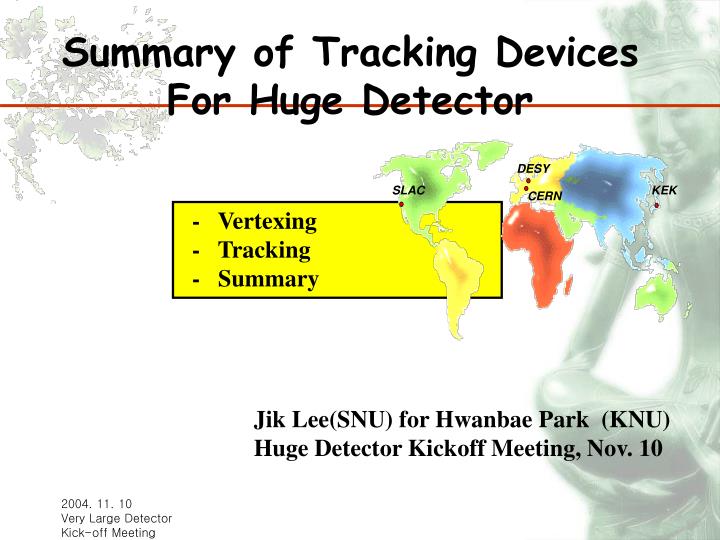
DESY. SLAC. KEK. CERN. Summary of Tracking Devices For Huge Detector. - Vertexing - Tracking - Summary. Jik Lee(SNU) for Hwanbae Park (KNU) Huge Detector Kickoff Meeting, Nov. 10. m. SC-coil. HCAL (Pb(Fe)/scinti or digital). W/Scinti ECAL. TPC. Si intermedi.-Trk.

E N D
DESY SLAC KEK CERN Summary of Tracking Devices For Huge Detector - Vertexing - Tracking - Summary Jik Lee(SNU) for Hwanbae Park (KNU) Huge Detector Kickoff Meeting, Nov. 10
m SC-coil HCAL (Pb(Fe)/scinti or digital) W/Scinti ECAL TPC Si intermedi.-Trk SiVTX pixel(cold version) ▣Concepts of Huge Detector • Huge Detector: best optimized for “PFA” - excellent momentum resolution - good separation of clusters/tracks maximize BL2
▣Vertexing Performance Requirements •excellent spacepoint precision < 4 microns • impact parameter resolution ≤ 5µm 10µm/(p sin3/2 ) • minimal multiple scattering 0.1-0.2% X0 or less per layer (transparency) • two track separation, occupancy 20 x 20 µm2 pixel size pixelated type • Charge Coupled Devices (CCD) • Monolithic Active Pixels (MAPs) • DEPleted Field Effect Transistor (DEPFET) • Silicon On Insulator (SOI) • Image Sensor with In-Situ Storage (ISIS)
▣ Beam Structures • Pileup over bunch train • Or fast timing • bx live: 3 10-5 • power pulse warm • Fast readouts: OK, no pileup • Digital pipeline • bx live: 5 10-3 cold • readout speed • radiation hardness • occupancy
CP CCD ▣ Vertex Detector: CCD • faster readout needed for cold machine - need to readout every 50 µs (20 times) during a train ~0.5% occupancy - use Column-Parallel CCD with low noise(increase readout speed ~50MHz) separate amplifier and readout for each column LCFI CP CCD 400x750 pixels(20µmx20µm) •cryostat for operation at 200 K - could be unnecessary withfast readout thin and mechanically stable ladder
▣ Image Sensor with In-situ Storage (ISIS) • •20 readouts/bunch train may be impossible due to beam –related RF pick up • motivates delayed operation of detector for long bunch train: • • charge collection to photogate from 20-30 µm silicon, as in a conventional CCD • • signal charge shifted into storage register every 50 µs, providing required time slicing • • string of signal charges is stored during bunch train in a buried channel, avoiding charge-voltage conversion • • totally noise-free charge storage, ready for readout in 200 ms of calm conditions between trains
▣ Vertex Detector: MAPS Prototype ▪ standard CMOS sensor technology - readout/sensor on one chip - signal is corrected from epi. layer ▪ pixel size and precision ~ CCD • neutron irradiations - fluencies up to 1012 neutrons/cm2 are acceptable with considering LC requirements which is ~ 109 n/cm2/year • ionizing irradiations - tests up to a few 100kRad - exact sources of performance losses are under investigation (diode size and placements of the transistors are important parameters) 5% drop in charge at 1.5e12 n/cm2
▣ Vertex Detector: DEPFET Prototype ▪ detector and amplification properties ▪ fully sensitivity over whole bulk ▪ very low noise operation at room temp. • thinning process for sensors established 800x104 mm2 - sensitive area 50µm thinned - fast signal to cope with high rate requirement - resolution of 9.5 μm for single pixel • complete clear no clear noise - (1 x clear) then sample 500x in 2.5ms - (clear + sample) 500x
▣Vertex Detector Issue • pair background hit at R=15mm is 1.7 times larger than that of 4T • background hits are decreased significantly at larger R • configuration of R=20mm with silicon thickness < 70 µm satisfies the impact parameter resolution requirement: ≤ 5µm 10µm/(p sin3/2 ) • readout speed and rad. hardness • very thin detector Y. Sugimoto
▣Tracking Performance Requirements • excellent momentum resolution - dilepton recoil mass for higgstrahlung process - end-point measurement for SUSY chains • excellent pattern recognition and 2 track resolution - high energy, high density jets • tolerant to high machine backgrounds -tracks in central tracker dominated by γγ events gaseous type (readout) • MWPC and pads - limited by positive ion feedback and MWPC response • MPGD’s (Micro Pattern Gas Detectors) - GEM (Gas Electron Multiplier) - MicroMEGAS (Micro Mesh GAS detector)
▣TPC with GEM • 50 µm Kapton foil for gas amplification • 5 µm copper coated on both sides • 70 µm holes, 140 µm pitch • hexagonally aligned holes • multiple GEM structures - safer operation - more flexibility to optimize charge transfer • GEM voltages up to 500 V yield 104 gas amplification
▣TPC with GEM • to reduce ion feedback -GEM with Micro Hole Strip Plate (MHSP) • apply negative strip voltage ions collected on strips, electrons extracted from holes due to diffusion IF is reduced by a factor of 4
S1 S2 ▣TPC with MicromeGAS • a micromesh sustained by 50-100 µm high insulating pillars • multiplication takes place btw anode and mesh • S1/S2 ~ Eamp/Edrift - can choose gap/HV to have gain maximum - ion feedback suppressed by Edrift/Eamp
▣TPC with MicromeGAS • 50 cm drift, 1024 channels • tested up to 2T at Saclay - no gain drop with 55Fe Field cage Detector pad layout: 1024 pads Readout Berkeley-Orsay-Saclay TPC principle is proven but optimization to be done
▣ TPC Tracking Issue • small structures (no ExB effects) • fast electron signal • intrinsic ion feedback suppression • optimize novel gas amplification systems • ion feedback suppression • neutron backgrounds • optimize single point and double track resolution • demonstrate large system performance with control of systematics
SET ▣Intermediate and Forward Tracker • improve momentum resolution • improve track finding efficiency • forward tracking • intermediate between vertex and central (IMT, SIT, FTD) • intermediate between central and calorimeters (FCH, SET) • located btw vtx and main tracker (GLC model) - 5 layers at r=9 to 37 cm - angular coverage |cosΘ|<0.9 - spatial resolution σ = 20μm - total amount of Si required: 10 m2 • SIT + TPC + SOT
64ch 50um pitch sensor 512ch 50um pitch sensor p+ implanted readout strip n+ implanted readout pad in staggering via in hourglass p-stop in atoll guard ring 32ch 50um pitch sensor 1cm PIN Diode 16ch 50um pitch sensor For SDD R&D PIN Diode array Backside of SSD N side P side ▣Intermediate Tracker
▣Tracking Devices • •Si Vertex Detector • 5 layers, t=70µm, =3µm • cos < 1 (non-realistic) • •Si Inner Tracker • 3 layers (12, 24, 36 cm), • t=300µm, =7 µm, cos<1 (non-realistic) • •TPC • 40cm < R < 200cm, Z<235cm • Ar gas, 220 samples, =150µm • •Si Outer Tracker • R=205cm(barrel)/Z=250cm(EC), • =7µm • detail (realistic) simulation studies are underway Y. Sugimoto ΔPt/pt2 Pt(GeV/c)
▣Vertexing/Tracking Issues • R&D must be guided by continuing physics and simulation programs which can deliver the accuracy that the LC physics needs -evaluate the tracking performance: backgrounds, occupancy studies, pattern recognition studies • demonstrate performance in large scale prototypes in cosmic ray and test beams studies with the magnetic field • vertex detector, tracker, calorimeters should be integrated for optimal jet reconstruction
▣Physics Performance • end-point measurement for SUSY chains GLC project report